


108
FX3G/FX3U/FX3UC Series Programmable Controllers
Programming Manual - Basic & Applied Instruction Edition
4 Devices in Detail
4.7 High Speed Counter [C] (FX3U/FX3UC PLC)
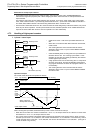
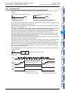
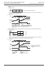
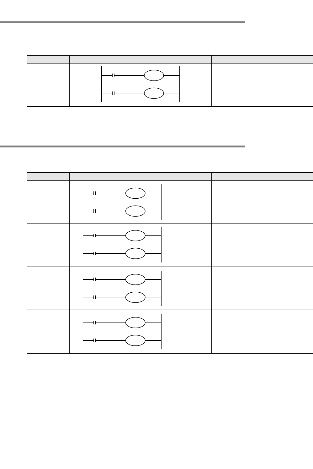
4.7.6 Changing the logic of external reset input signal
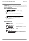
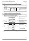
The counters C241 to C245, C247 to C250 and C252 to C255 are usually reset when the external reset input turns
ON.
By using the program shown below, the logic can be inverted so that these counters are reset when the external reset
input turns OFF.
Caution
The counter C253 is switched to a software counter when the logic of the external reset input signal is inverted.
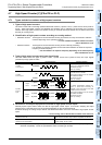
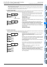
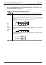
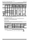
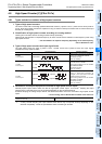
4.7.7 Assignment of counter input terminal and switching of function
The assignment of the input terminal and the function of the software counters C244, C245, C248 and C253 are
changed as shown below when combined with the following special auxiliary relays.
In a program, put a special auxiliary relay just before a target counter.
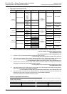
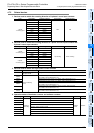
Counter No. When inverting logic of external reset input signal Description
C241 to C245
C247 to C250
C252 to C255
The logic of the external reset input is inverted
so that the counters are reset when the input
turns OFF.
(The logic is inverted for all target counters.)
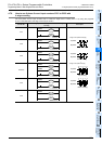
Counter No. When using software counter as hardware counter Description
C244(OP)
• The counting input is changed from X000 to
X006.
• Reset input is not provided.
• Start input is not provided.
• It operates as a hardware counter.
C245(OP)
• The counting input is changed from X002 to
X007.
• Reset input is not provided.
• Start input is not provided.
• It operates as a hardware counter.
C248(OP)
• Reset input is not provided.
• It operates as a hardware counter.
C253(OP)
• Reset input is not provided.
• It operates as a software counter.
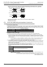
M8388
M8389
C2
K
{{{
M8388
M8390
C244
K
{{{
M8388
M8391
C245
K
{{{
M8388
M8392
C248
K
{{{
M8388
M8392
C253
K
{{{