


455
FX3G/FX3U/FX3UC Series Programmable Controllers
Programming Manual - Basic & Applied Instruction Edition
16 External FX Device – FNC 80 to FNC 89
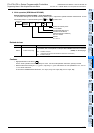
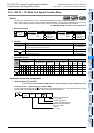
16.1 FNC 80 – RS / Serial Communication
11
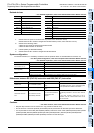
FNC30-FNC39
Rotation and
Shift
12
FNC40-FNC49
Data Operation
13
FNC50-FNC59
High Speed
Processing
14
FMC60-FNC69
Handy
Instruction
15
FNC70-FNC79
External FX I/O
Device
16
FNC80-FNC89
External FX
Device
17
FNC100-FNC109
Data
Transfer 2
18
FNC110-FNC139
Floating Point
19
FNC140-FNC149
Data
Operation 2
20
FNC150-FNC159
Positioning
Control
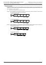
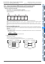
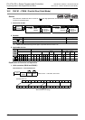
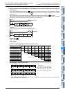
Related devices
→ For detailed explanation, refer to the Data Communication Edition manual.
*1. Cleared when the power is turned off and on (in FX
3G, FX3U and FX3UC PLCs).
Cleared when the PLC mode is changed from STOP to RUN (in FX
3G, FX3U and FX3UC PLCs).
*2. Cleared in the following cases:
• When the PLC mode is changed from RUN to STOP
• When the RS instruction is not driven
*3. Latched (battery or EEPROM backed).
*4. Cleared when the PLC mode is changed from RUN to STOP.
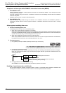
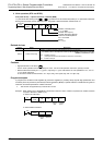
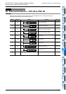
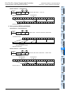
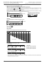
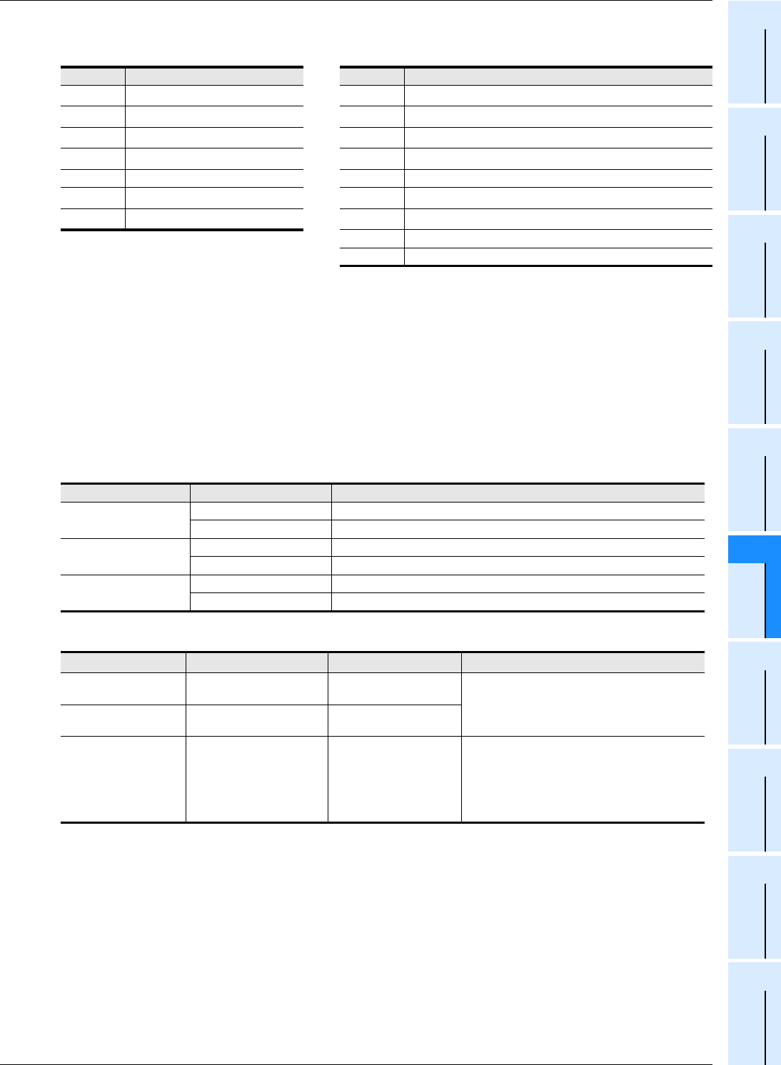
System configuration
To use this instruction, it is necessary to attach one of the products shown in the table below to the main unit.
→ For the system configuration, refer to the respective PLC Hardware Edition manual.
→ For detailed explanation, refer to the Data Communication Edition manual.
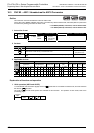
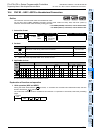
Differences between RS (FNC 80) instruction and RS2 (FNC 87) instruction
Cautions
→ For other cautions, refer to the Data Communication Edition manual.
• RS (FNC 80) instruction can be used for ch1 only (cannot be used for ch2).
• Do not drive two or more RS (FNC 80) and/or RS2 (FNC 87) instructions for the same port at the same time.
• It is not permitted to use an RS (FNC 80)/RS2 (FNC 87) instruction and an IVCK (FNC270)/IVDR (FNC271)/IVRD
(FNC272)/IVWR (FNC273)/IVBWR (FNC274)/FLCRT (FNC300)/FLDEL (FNC301)/FLWR (FNC302)/FLRD
(FNC303)/FLCMD (FNC304)/FLSTRD (FNC305) instruction for the same port.
Device Name Device Name
M8063
*1
Serial communication error 1
D8120
*3
Communication format setting
M8121
*2
Sending wait flag
D8122
*4
Remaining amount of data to be sent
M8122
*2
Sending request
D8123
*4
Amount of data already received
M8123
*2
Receiving complete flag D8124 Header
M8124 Carrier detection flag D8125 Terminator
M8129 Time-out check flag
D8129
*3
Time-out time setting
M8161
*4
8-bit processing mode
D8063
*1
Error code number of serial communication error 1
D8405 Communication parameter display
D8419 Operation mode display
PLC Communication type Option
FX
3U,
FX
3UC-32MT-LT(-2)
RS-232C communication FX3U-232-BD or FX3U-232ADP(-MB) (with FX3U-CNV-BD)
RS-485 communication FX
3U-485-BD or FX3U-485ADP(-MB) (with FX3U-CNV-BD)
FX
3UC(D,DSS)
RS-232C communication FX
3U-232ADP(-MB)
RS-485 communication FX
3U-485ADP(-MB)
FX
3G
RS-232C communication FX3G-232-BD or FX3U-232ADP(-MB) (with FX3G-CNV-ADP)
RS-485 communication FX
3G-485-BD or FX3U-485ADP(-MB) (with FX3G-CNV-ADP)
Item
RS2 instruction
RS instruction Remarks
Header size 1 to 4 characters (bytes)
Up to 1 character
(byte)
For the RS2 instruction, up to 4 characters (bytes)
can be specified as a header or terminator.
Terminator size 1 to 4 characters (bytes)
Up to 1 character
(byte)
Attachment of check
sum
The check sum can be
automatically attached.
The check sum should be
attached by a user
program.
For the RS2 instruction, the check sum can be
automatically attached to the sent and received
data.
In this case, however, make sure to use a
terminator with the communication frame to be
sent and received.