


438
FX3G/FX3U/FX3UC Series Programmable Controllers
Programming Manual - Basic & Applied Instruction Edition
15 External FX I/O Device – FNC 70 to FNC 79
15.6 FNC 75 – ARWS / Arrow Switch
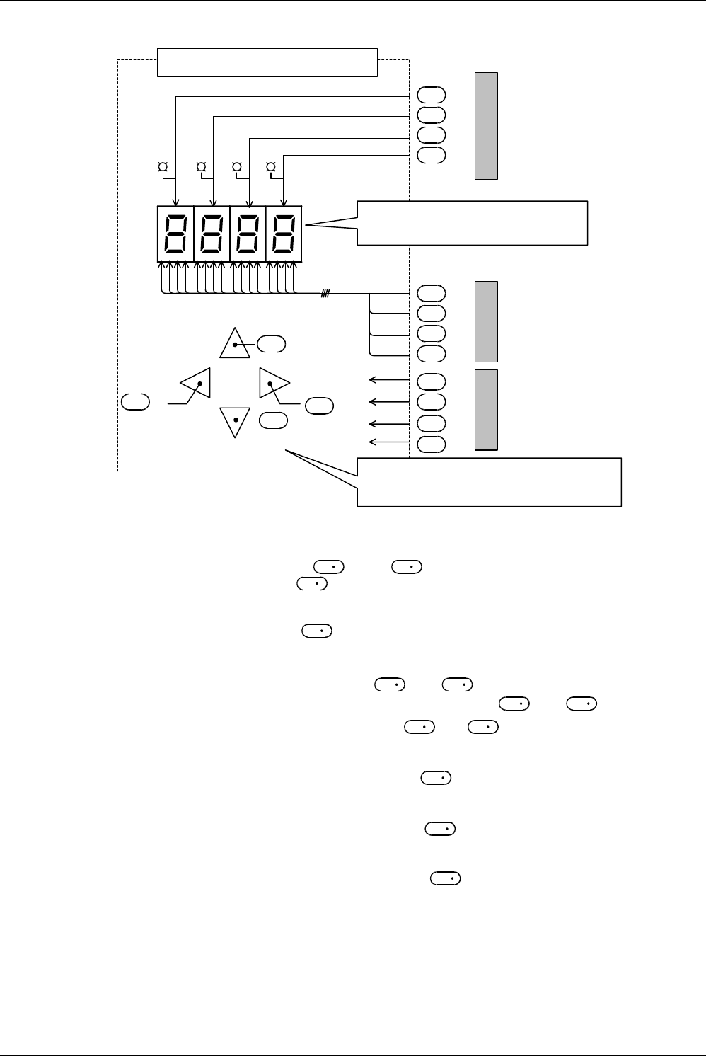
Contents of the display and operation part
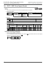
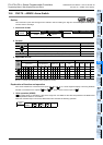
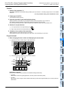
1) Specifying the number of digits of the seven-segment display unit having the BCD decoder n
In the explanation below, "n" is set to "4" (up to the 10
3
digit).
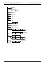
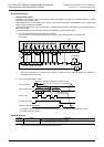
2) Operation of the digit selection switches ( +2 and +3)
- Operation when the lower digit input +2 turns ON
Every time the lower digit switch is pressed, the digit specification changes in the way "10
3
→ 10
2
→ 10
1
→ 10
0
→ 10
3
".
- Operation when the higher digit input +3 turns ON
Every time the higher digit switch is pressed, the digit specification changes in the way "10
3
→ 10
0
→ 10
1
→ 10
2
→ 10
3
".
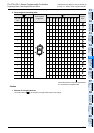
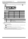
3) Operation of the LED for displaying a selected digit ( +4 to +7)
A specified digit can be displayed by the LED offered by the strobe signals +4 to +7.
4) Operation of the switches for changing data in each digit ( and +1)
In a digit specified by a digit selection switch described above, data is changed as follows:
- When the increment input turns ON
Every time the increment switch is pressed, the contents of change in the way "0 → 1 → 2 → ... → 8 → 9
→ 0 → 1".
- When the decrement input turns ON
Every time the decrement switch is pressed, the contents of change in the way "0 → 9 → 8 → 7 ... 1 → 0
→ 9".
The contents can be displayed in the seven-segment display unit.
As described above, a target numeric value can be written to using a series of operation while looking at
the seven-segment display unit.
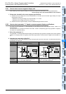
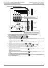
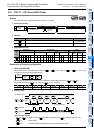
Display/operation panel
1
2
4
8
10
0
10
1
10
3
10
2
←
Display for
selected digit
Decrement
Increment
Higher
digit
Lower
digit
+3
+7
+2
+4
+6
+5
+3
+1
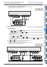
Seven-segment display unit
Equipped with the latch function so that a
numeric value being set can be seen.
Arrow switches
Provided to select a digit and increment or
decrement the numeric value in the selected digit.
Strobe output
Numeric value
output
Switches
+2
+3
+1
To outputs in
PLC
To outputs in
PLC
To inputs in
PLC
+1
+2
S
S
S
S
D
2
D
2
D
2
D
2
D
2
D
2
D
2
D
2
S
S
S
S
S
S
S
S
D
2
D
2
D
2
D
2
S
S
D
1
D
1
D
1