


74
S:\agilent\e8285\REFGUIDE\MANUAL\connectr.chp
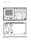
Chapter 2, Description of Connectors
Connectors
MODULATION INPUT
This connector provides an external modulation connection to the RF Generator.
Operating Considerations
Input impedance = 600Ω
Maximum input level = 12 V peak
Full scale input = 1 V peak
The
Mod In To field of the RF GENERATOR screen sets the type of modulation
(AM or FM) and sensitivity (%AM/Vpk or kHz/Vpk) for this connection.
The
FM Coupling field in the RF GENERATOR, DUPLEX TEST, and various
encoder modes selects ac or dc coupling of this signal for FM operation.
PAGING CHANNEL LOGGING (DCS2>)
The Paging Channel Logging port provides for logging protocol signaling from
the Paging channel. Refer to Protocol Logging in the Application Guide.
Operating Considerations
• 9-pin sub-miniature D
• 115.2k Baud
•8 bit
• No parity
• No flow control
Pin assignments for this connector are as follows::
Pin 1 - Not Used
Pin 2 - RX_A, RS-232
Pin 3 - TX_A, RS-232
Pin 4 - Not Used
Pin 5 - Ground
Pin 6 - Not Used
Pin 7 - Reserved
Pin 8 - Reserved
Pin 9 - Not Used