


70
S:\agilent\e8285\REFGUIDE\MANUAL\connectr.chp
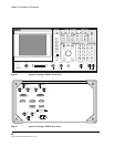
Chapter 2, Description of Connectors
Connectors
CELL SITE/TRIGGERS
This is a DB-25 connector. It provides various CDMA triggers and digital cell
diagnostics.
Operating Considerations
• Pins 1, 2, 3 Ground
• Pin 4 - Closed Loop Power Control Ramp Down (CSD1_TRIG1)
TTL, 1.8
µ
s positive pulse indicating ramp down beginning.
NOTE: This trigger does not align exactly with the outgoing power control bit in the RF signal. It
occurs about 72 microseconds before the next 1.25 ms clock edge.
• Pin 5 - Reserved (AMB_TRIG_OUT)
• Pin 6 - Ground
• Pin 7 - DSP TRIG IN, TTL
• Pin 8 - Reserved (HDSET_TX+)
• Pin 9 - Reserved (HDSET_RX+)
• Pin 10 - Ground
• Pin 11 - Reserved (AMB_PDC_DATA_IN
• Pins 12, 13 - No connect
• Pin 14 - Baseband I modulation signal (I_MOD_DRIVE)
120 mVrms, nominal into 50 ohms.
• Pin 15 - Baseband Q modulation signal (Q_MOD_DRIVE)
120 mVrms, nominal into 50 ohms.
• Pin 16 - Closed Loop Power Control Ramp Up (CSD1_TRIG0)
TTL, 1.8
µ
s positive pulse indicating ramp up beginning.
NOTE: This trigger does not align exactly with the outgoing power control bit in the RF signal. It
occurs about 72 microseconds from the next 1.25 ms clock edge.
• Pin 17 - Reserved (CSD1_TRIG2)
TTL
• Pin 18 - Reserved (DSP2_TRIG_OUT)
• Pin 19 - External scope trigger input (EXT_TRIG_IN)
TTL
• Pin 20 - Ground
• Pin 21 - Reserved
• Pin 22 - Reserved
• Pin 23 - Reserved
• Pin 24 - Ground
• Pin 25 - No Connect