


Appendix - 98
MELSEC-Q
APPENDICES
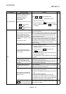
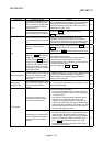
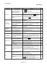
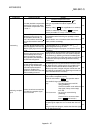
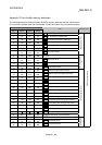
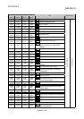
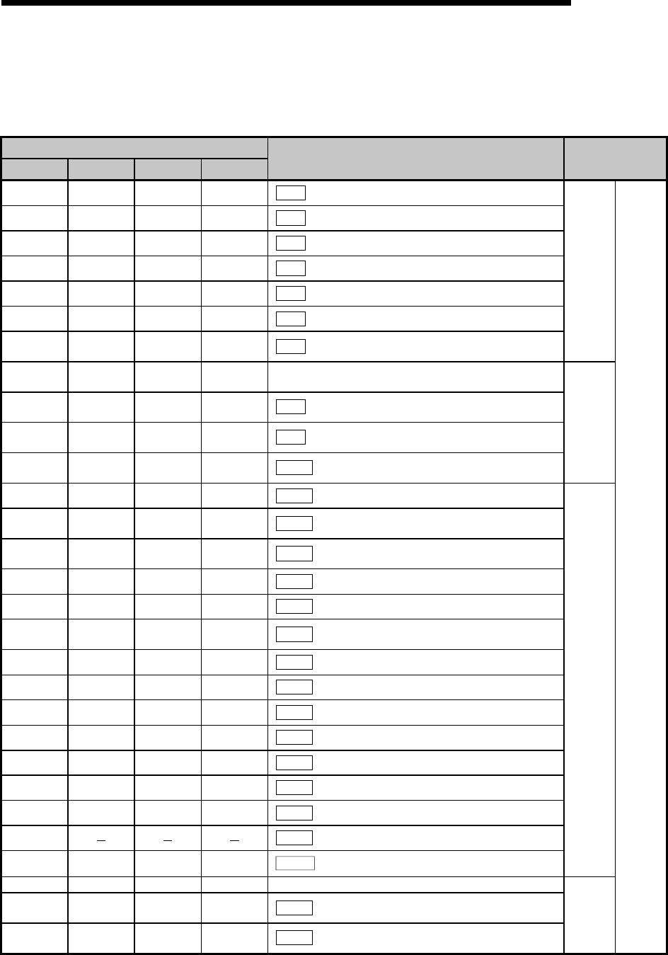
Appendix 12 List of buffer memory addresses
The following shows the relation between the buffer memory addresses and the various items.
(Do not use ary address other than listed below. If used, the system may not operate correctly.)
Buffer memory address
Axis 1 Axis 2 Axis 3 Axis 4
Item Memory area
0 150 300 450
Pr.1
Unit setting
1 151 301 451
Pr.2
No. of pulses per rotation (Ap)
2 152 302 452
Pr.3
Movement amount per rotation (Al)
3 153 303 453
Pr.4
Unit magnification (Am)
4 154 304 454
Pr.5
Pulse output mode
5 155 305 455
Pr.6
Rotation direction setting
6
7
156
157
306
307
456
457
Pr.7
Bias speed at start
Basic parameters 1
8
9
158
159
308
309
458
459
Not used
10
11
160
161
310
311
460
461
Pr.8
Speed limit value
12
13
162
163
312
313
462
463
Pr.9
Acceleration time 0
14
15
164
165
314
315
464
465
Pr.10
Deceleration time 0
Basic parameters
2
17 167 317 467
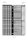
Pr.11
Backlash compensation amount
18
19
168
169
318
319
468
469
Pr.12
Software stroke limit upper limit value
20
21
170
171
320
321
470
471
Pr.13
Software stroke limit lower limit value
22 172 322 472
Pr.14
Software stroke limit selection
23 173 323 473
Pr.15
Software stroke limit valid/invalid selection
24
25
174
175
324
325
474
475
Pr.16
Command in-position width
26 176 326 476
Pr.17
Torque limit setting value
27 177 327 477
Pr.18
M code ON signal output timing
28 178 328 478
Pr.19
Speed switching mode
29 179 329 479
Pr.20
Interpolation speed designation method
30 180 330 480
Pr.21
Current feed value during speed control
31 181 331 481
Pr.22
Input signal logic selection
32 182 332 482
Pr.23
Output signal logic selection
33
Pr.24
Manual pulse generator input selection
34 184 334 484
Pr.150
Speed-position function selection
Detailed parameters 1
35 185 335 485 Not used
36
37
186
187
336
337
486
487
Pr.25
Acceleration time 1
38
39
188
189
338
339
488
489
Pr.26
Acceleration time 2
Detailed
parameters
2
Positioning parameters