


5 - 80
MELSEC-Q
5 DATA USED FOR POSITIONING CONTROL
5.5 List of condition data
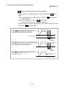
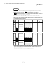
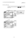
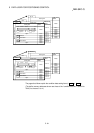
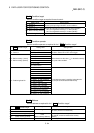
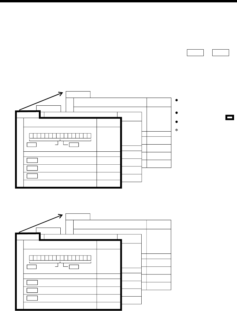
The illustrations below show the organization of the condition data stored in the QD75
buffer memory. The condition data setting items
Da.15
to
Da.19
are explained in the
pages that follow.
No.10
Setting item
26190
26191
26192
26193
26194
26195
26196
26197
26198
26199
No.2
Setting item
26110
26111
26112
26113
26114
26115
26116
26117
26118
26119
Buffer memory
address
Buffer memory
address
No.1
Setting item
26100
Da.17 Address
Open
Da.18 Parameter 1
Da.19 Parameter 2
b15 b0
b7
b8b11b12
Da.16 Condition
operator
Da.15 Condition
target
26101
26102
26103
26104
26105
26106
26107
26108
26109
Buffer memory
address
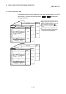
Axis 1 (start block 0)
Open
Up to 10 block start data points can be set (stored)
for each axis in the buffer memory addresses shown
on the left.
Items in a single unit of condition data are shown
included in a bold frame.
Each axis has five start blocks (block Nos. 0 to 4).
For information on the organization of the buffer
memory addresses assigned to the start blocks 1
to 4, refer to Appendix 12 "List of buffer memory
addresses".
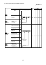
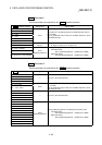
No.10
Setting item
No.2
27190
27191
27192
27193
27194
27195
27196
27197
27198
27199
27110
27111
27112
27113
27114
27115
27116
27117
27118
27119
Setting item
No.1
Setting item
27100
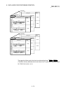
Da.17 Address
Open
Open
Da.18 Parameter 1
Da.19 Parameter 2
b15 b0
b7
b8b11b12
Da.16 Condition
operator
Da.15 Condition
target
27101
27102
27103
27104
27105
27106
27107
27108
27109
Buffer memory
address
Axis 2 (start block 0)
Buffer memory
address
Buffer memory
address