


12 - 32
MELSEC-Q
12 CONTROL SUB FUNCTIONS
12.4.4 Hardware stroke limit function
!
DANGER
When the hardware stroke limit is required to be wired, ensure to wire it in the negative logic using b-contact.
If it is set in positive logic using a-contact, a serious accident may occur.
In the "hardware stroke limit function", limit switches are set at the upper/lower limit of
the physical moveable range, and the control is stopped (by deceleration stop) by the
input of a signal from the limit switch. Damage to the machine can be prevented by
stopping the control before the upper/lower limit of the physical moveable range is
reached.
Hardware stroke limit switches are normally installed inside the stroke limit/stroke end
on the drive unit side, and the control is stopped before the stroke limit/stoke end on
the drive unit side is reached.
The details shown below explain about the "hardware stroke limit function".
[1] Control details
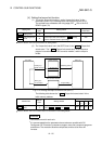
[2] Wiring the hardware stroke limit
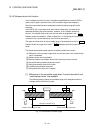
[3] Precautions during control
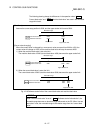
[4] When the hardware stroke limit is not used
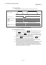
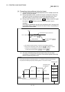
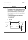
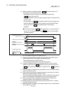
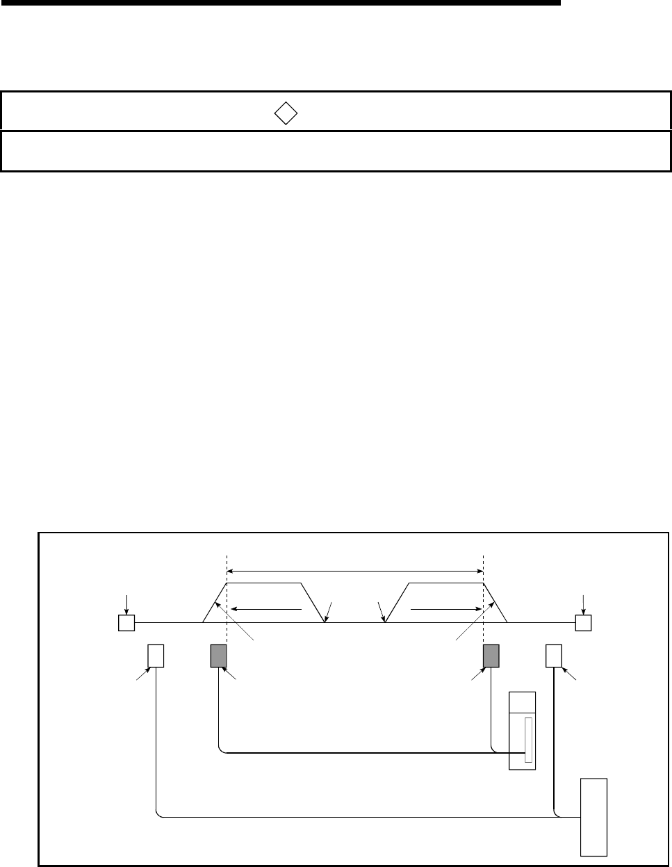
[1] Control details
The following drawing shows the operation of the hardware stroke limit function.
Mechanical stopper
Drive unit
QD75
Movement direction
Deceleration stop at
upper limit switch detection
QD75 control moveable range
Lower limit
Upper limit
Start
Upper limit switchLower limit switch
Drive unit
stroke limit
Drive unit
stroke limit
Start
Movement direction
Mechanical stoppe
r
Deceleration stop at
lower limit switch detection
Fig. 12.19 Hardware stroke limit function operation