3 - 24
MELSEC-Q
3 SPECIFICATIONS AND FUNCTIONS
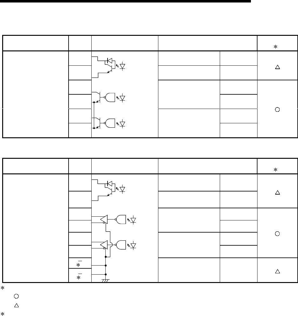
(2) Output (For QD75P1)
External wiring Pin No. Internal circuit Signal name
Need for wiring
1
1A13 Deviation counter clear CLEAR
1A14 Common CLEAR COM
1A15 PULSE F
1A16
CW
A phase
PULSE
PULSE COM
1A17 PULSE R
1A18
CCW
B phase
SIGN
PULSE COM
(3) Output (For QD75D1)
External wiring Pin No. Internal circuit Signal name
Need for wiring
1
1A13 Deviation counter clear CLEAR
1A14
Common CLEAR COM
1A15 PULSE F+
1A16
CW
A phase
PULSE
PULSE F–
1A17
PULSE R+
1A18
CCW
B phase
SIGN
PULSE R–
2
2
Differential driver
common terminal
SG
1: The symbols in Need for wiring column indicate the following meanings:
• : Wiring is necessary for positioning.
•
: Wiring is necessary depending on the situation.
2: A terminal block at the bottom of the module. (Refer to Section 4.1.2)


