


12 - 53
MELSEC-Q
12 CONTROL SUB FUNCTIONS
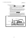
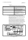
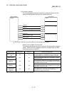
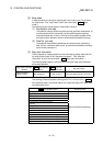
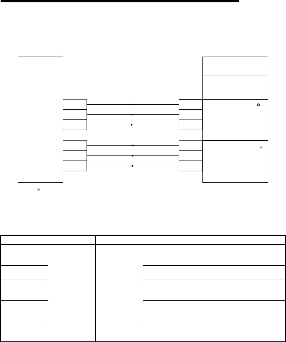
(3) Connection example
The following diagram shows the example of connection between the PLC
system and the Mitsubishi Electric servo amplifier (MR-H-A).
<Servo amplifier> <PLC system>
24(PF)
25(TLC)
23(ZSP)
12(SON)
44(DI3)
45(DI4)
0(X47)
1(X48)
2(X49)
0(Y50)
1(Y51)
2(Y52)
ABS bit0
ABS bit1
Transmission data preparation completed
Servo ON
ABS transmission mode
ABS request
MR-H-A QCPU
QD75
16 points input module
16 points output module
: The X and Y devices can be set arbitrarily with the sequence program.
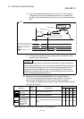
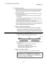
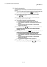
Details of servo amplifier connector pins
The following table shows the pins for setting the "absolute position detection
system". Refer to the MR-H operation manual for the details when the ABS
transmission mode is turned OFF.
Signal name Abbreviation Pin No. Function and application
ABS transmission
mode
DI3 44
ABS transmission mode terminal. While this is turned ON,
the servo amplifier is in the ABS transmission mode, and
the DI4/PF/ZSP/TLC functions are as shown in this table.
ABS request DI4 45
This is turned ON when ABS data is requested in the ABS
transmission mode.
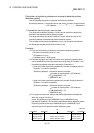
ABS bit 0 PF 24
This indicates the lower order bit among 2 bits of ABS data
to be transferred from the servo amplifier to the PLC system
in the ABS transmission mode.
ABS bit 1 ZSP 23
This indicates the upper order bit among 2 bits of ABS data
to be transferred from the servo amplifier to the PLC system
in the ABS transmission mode.
Transmission data
preparation
completed
TLC 25
This indicates the transmission data preparation completed
in the ABS transfer mode. When the preparation is
completed, the signal is turned ON.
Refer to the MR-H operation manual for the I/O interface.