


14 - 16
MELSEC-Q
14 DEDICATED INSTRUCTIONS
14.6 PFWRT
These dedicated instructions are used to write the QD75 parameters, positioning data
and block start data to the flash ROM.
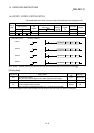
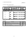
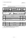
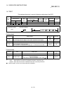
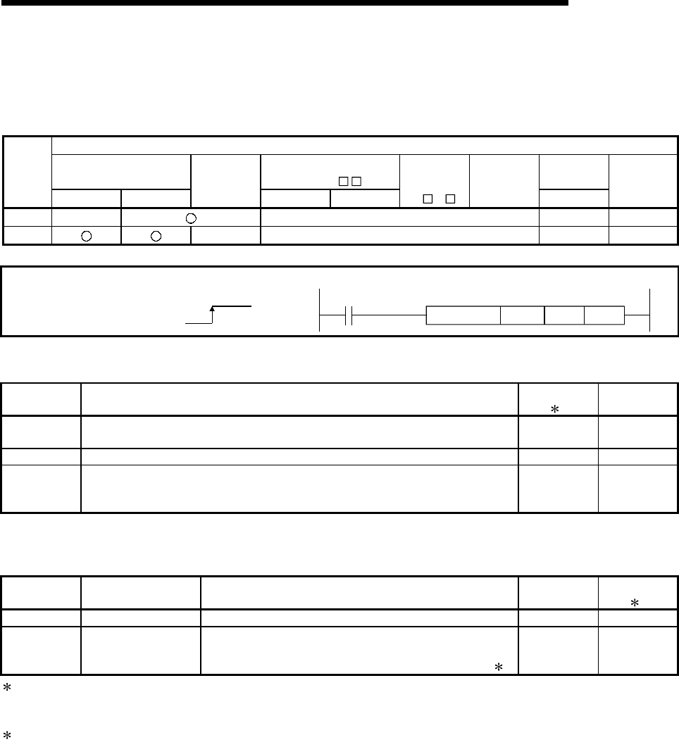
Usable device
Internal device
MELSECNET/10
direct J
\
Constant
Setting
data
Bit Word
File
register
Bit Word
Special
module
U
\G
Index
register
Zn
K, H, $
Others
(S) – –––
(D) ––––
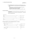
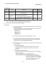
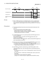
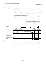
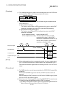
[Instruction symbol] [Execution condition]
PFWRT
ZP.PFWRT "Un" (S) (D)
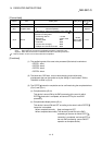
[Setting data]
Setting data Setting details
Setting side
(
1)
Data type
"Un"
QD75 head I/O number
(00 to FE: High-order two digits of I/O number expressed in three digits)
User BIN 16 bits
(S) Head number of a device in which control data is stored – Device
(D)
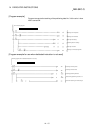
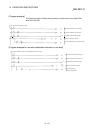
Head number of a bit device which turns ON the operation by one scan at the
time of completion of the instruction.
If the instruction is completed abnormally, ((D) + 1) will also be turned ON.
System Bit
Note) The file register of each of the local device and the program cannot be used as a device for setting data.
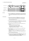
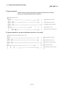
[Control data]
Device Item Setting data
Setting
Range
Setting side
(
1)
(S)+0 System area – – –
(S)+1 Complete status
The state at the time of completion is stored.
0 : Normal completion
Other than 0 : Abnormal completion (error code)(
2)
–System
1: The data on the setting side is as follows.
• User : Data before the execution of dedicated instructions is stored by user.
• System: Data after the execution of dedicated instruction is stored by PLC CPU.
2: Refer to Section 15.2 for error codes at abnormal completion.