


Appendix - 69
MELSEC-Q
APPENDICES
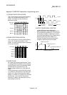
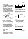
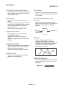
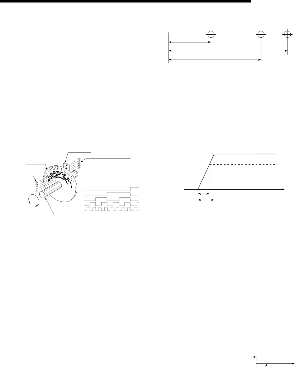
ABSOLUTE ENCODER
This is a detector that enables the angle data
within 1 motor rotation to be output to an
external destination. Absolute encoders are
generally able to output 360
°
in 8 to 12 bits.
Incremental encoders have a disadvantage in
that the axis position is lost when a power
failure occurs. However, with absolute
encoders, the axis position is not lost even
when a power failure occurs.
Various codes such as a binary code and BCD
code can be output.
Absolute encoders are more expensive, more
accurate, and larger than incremental
encoders. Refer to "ENCODER".
2
2
2
2
0
1
3
4
2
4
2
3
2
2
2
1
2
0
Slit disk
Phototransistor
Fixed slit
Light-emitting diode
Rotating
axis
Binary code
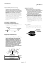
ABSOLUTE POSITION DETECTION
SYSTEM
In the absolute position detection system, once
an OPR is carried out at the system startup,
the system stores the machine position in the
memory and retains the current position even
when the power is turned OFF. Mechanical
deviation will be compensated, so that the
OPR is not required after the power is turned
ON next time. Configuring this system requires
a motor with an absolute position detector and
a servo amplifier and positioning module
compatible with an absolute position detection
system.
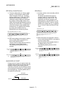
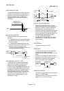
ABSOLUTE SYSTEM
This is one system for expressing a positioning
address.
Absolute address system.
This system uses 0 as a reference, and
expresses the address as the distance from 0.
The direction is automatically determined, even
when it is not designated. The other address
system is the increment system.
No.10 No.2 No.3
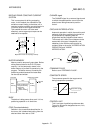
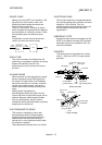
ACCELERATION TIME
The parameter acceleration time refers to the
time from a stopped state to the time the speed
limit value is reached, so it becomes
proportionally shorter as the setting speed
decreases. The acceleration time is determined
by factors such as machine inertia, motor
torque, and load resistance torque.
Speed limit value
Setting speed
Speed 0
Acceleration time
Time
ADDRESS
1) This is a numerical value to express the
positioning position, designated in mm,
inch, angle, or No. of pulse units.
2) The memory address. Many addresses are
stored in the memory. An address is read
or written after it is designated.
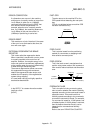
AFTER mode
This is the mode that outputs the M code after
positioning is complete (after stopping).
Clamping can be commanded, drilling
dimensions can be selected, etc., with this
mode.
OF
F
ON
No.11No.10
Positioning
M code (8)
Clamp command