


1 - 13
MELSEC-Q
1 PRODUCT OUTLINE
QD75 PLC CPU
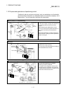
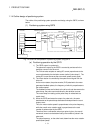
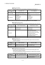
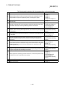
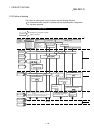
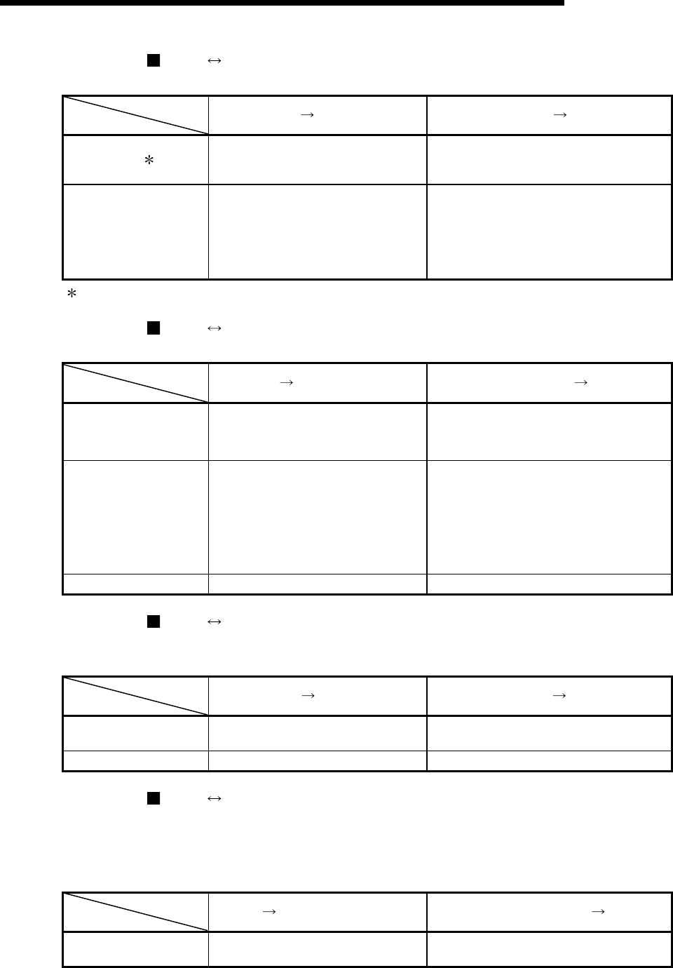
The QD75 and PLC CPU communicate the following data via the base unit.
Direction
Communication
QD75
PLC CPU PLC CPU QD75
Control signal
Signal indicating QD75 state, such as
QD75 READY signal, BUSY signal.
Signal related to commands such as PLC
READY signal, various start signals, stop
signals
Data (read/write)
• Parameter
• Positioning data
• Block start data
• Control data
• Monitor data
• Parameter
• Positioning data
• Block start data
• Control data
Refer to Section 3.3 "Specifications of input/output signals with PLC CPU" for details.
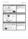
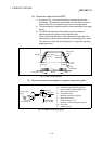
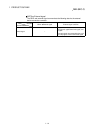
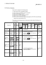
QD75 Peripheral device
The QD75 and peripheral device communicate the following data via the PLC CPU:
Direction
Communication
QD75
Peripheral device Peripheral device QD75
Data (read/write)
• Parameter
• Positioning data
• Block start data
• Parameter
• Positioning data
• Block start data
Test operation –
• OPR control start command
• Positioning control start command
• JOG/Inching operation start command
• Teaching start command
• Manual pulse generator operation
enable/disable command
Operation monitor • Monitor data –
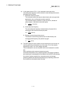
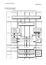
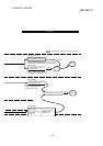
QD75 Drive unit
The QD75 and drive unit communicate the following data via the external device
connection connector.
Direction
Communication
QD75
Drive unit Drive unit QD75
Control signal
Signals related to commands such as
deviation counter clear signal
Signals indicating drive unit state such as
drive unit READY signal
Pulse train • Pulse train output –
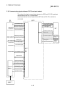
QD75 Manual pulse generator
The QD75 and manual pulse generator communicate the following data via the
external device connection connector.
(The manual pulse generator should be connected to an external device connection
connector for axis 1 or for axes 1 and 2.)
Direction
Communication
QD75
Manual pulse generator Manual pulse generator QD75
Pulse signal –
Manual pulse generator A-phase, manual
pulse generator B-phase