


Appendix - 67
MELSEC-Q
APPENDICES
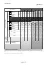
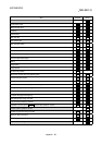
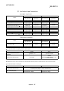
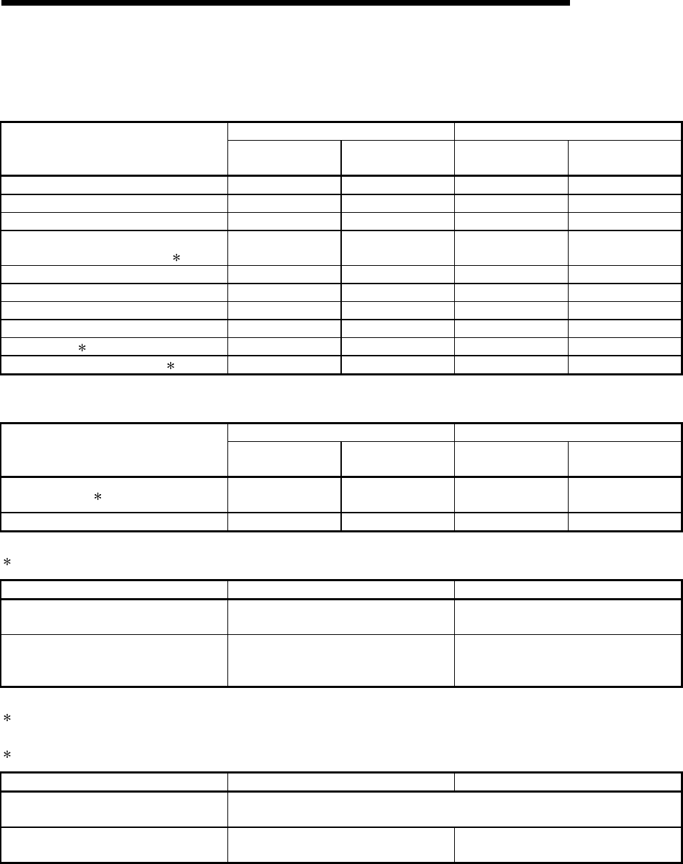
(6) Input/output signal comparisons
Input signal comparisons
A1SD75 QD75
Name
Logic (initial status)
Logic switch with
parameters
Logic (initial status)
Logic switch with
parameters
Drive unit READY Negative logic Not possible Negative logic Possible
In-position signal Negative logic Not possible – –
Zero signal Negative logic Not possible Negative logic Possible
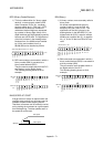
Manual pulse generator A phase
Manual pulse generator B phase
1
Negative logic
(multiple of 4)
Not possible
Negative logic
(multiple of 4)
Possible
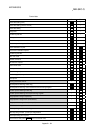
Near-point signal Negative logic Not possible Negative logic Possible
Stop signal Negative logic Not possible Negative logic Possible
Upper limit Negative logic Not possible Negative logic Possible
Lower limit Negative logic Not possible Negative logic Possible
External start 2 Negative logic Not possible Negative logic Possible
Speed-position switching signal 2 Negative logic Not possible Negative logic Possible
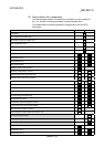
Output signal comparisons
A1SD75 QD75
Name
Logic (initial status)
Logic switch with
parameters
Logic (initial status)
Logic switch with
parameters
Command pulse 3
Positive logic
CW/CCW mode
Possible
Negative logic
CW/CCW mode
Possible
Deviation counter clear Negative logic Not possible Negative logic Possible
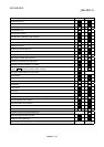
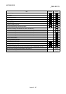
1: Comparisons about manual pulse generator A phase/B phase
A1SD75 QD75
No. of connectable manual pulse
generators
1 generator/1 axis 1 generator/1 module
Mode selection (with parameter) Not possible
Possible
Multiple of 1 mode, multiple of 4 mode,
PULSE/SIGN mode
2: With the QD75, the "external start signal" and "speed-position switching signal" are combined into the "external command signal".
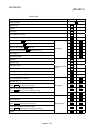
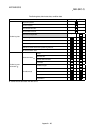
3: Comparisons about command pulse
A1SD75 QD75
Mode selection (with parameter)
PULSE/SIGN mode, A phase/B phase (multiple of 4) mode,
A phase/B phase (multiple of 1) mode, CW/CCW mode
Max. command frequency
Open collector: 200kpps
Differential driver: 400kpps
Open collector: 200kpps
Differential driver: 1Mpps