


15 - 23
MELSEC-Q
15 TROUBLESHOOTING
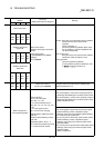
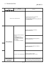
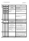
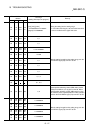
Related buffer memory
address
Axis 1 Axis 2 Axis 3 Axis 4
Set range
(Setting with sequence program)
Remedy
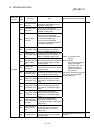
ABS setting direction in the
unit of degree
1550 1650 1750 1850
0: Shortcut
1: Clockwise
2: Counterclockwise
• Set the ABS setting direction in the unit of degree
within the setting range.
• Set "0" when the software stroke limits are valid.
(Refer to Section 9.1.5)
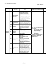
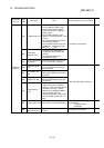
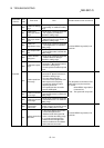
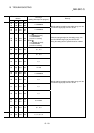
Software stroke limit
upper limit
18
19
168
169
318
319
468
469
Software stroke limit
lower limit
20
21
170
171
320
321
470
471
• [mm] [inch] [pulse]
–2147483648 to 2147483647
• [degree]
0 to 35999999
Invalidate the software stroke limit.
(To invalidate, set the software stroke limit upper limit
value to the software stroke limit lower limit value.)
(Refer to Section 9.1.5)
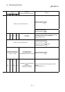
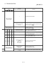
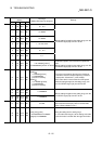
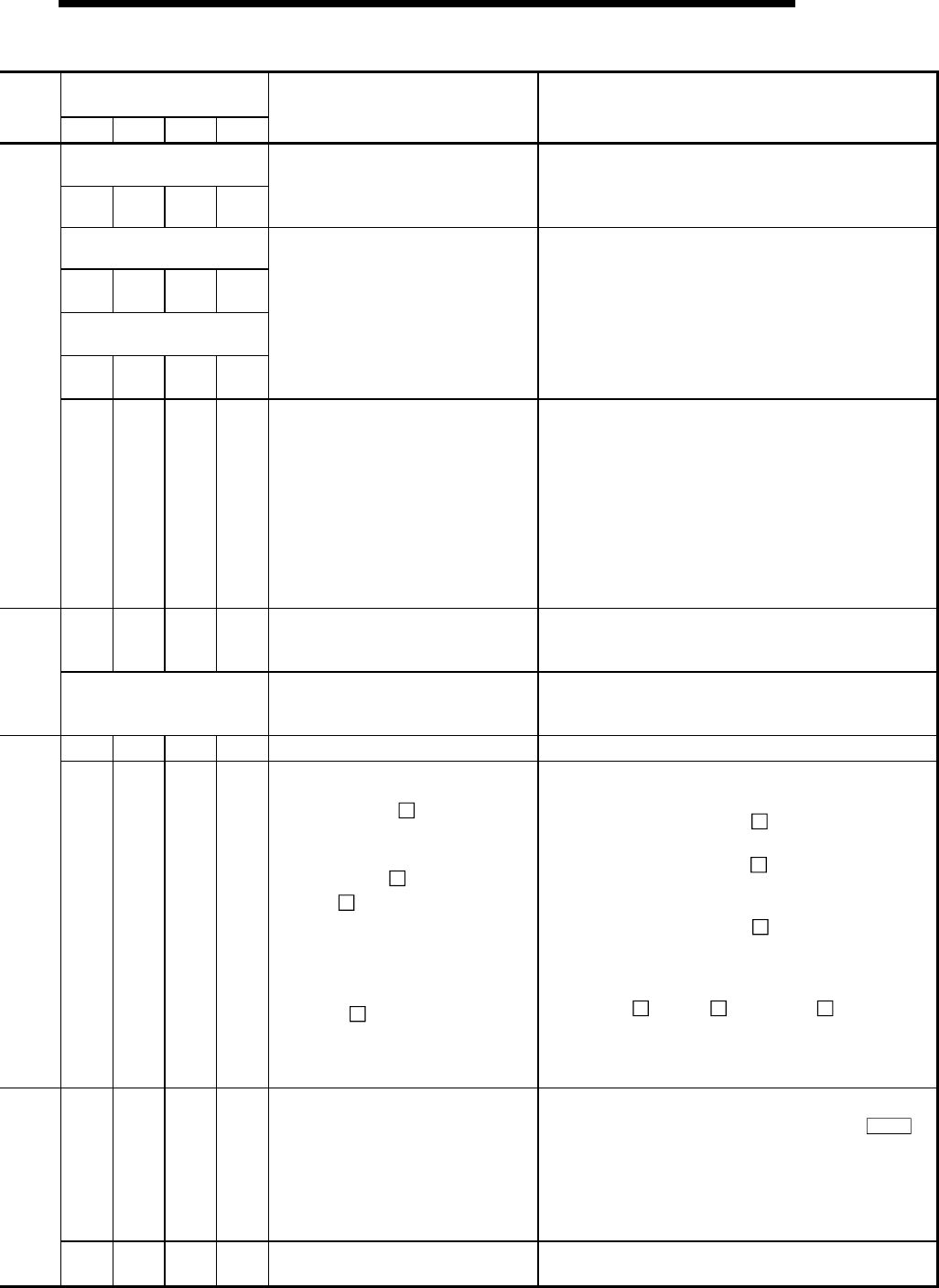
———— —
Clear the setting of the PLC CPU module parameter
"Output at error stop".
(Refer to "QCPU User’s Manual")
———— —
The flash ROM is expected to be at the end of its
writable life.
Replace the flash ROM with a new one.
1901
<Parameter initialization request>
1: Parameter initialization is
requested
Return the parameter to that set at the time of delivery
from the plant. (Refer to Section 13.2)
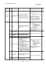
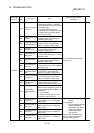
— — — — — (Refer to "QCPU User’s Manual")
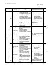
————
<ABRST status>
0: Communication complete
(received from the servo amplifier)
<PSTRT start No.>
<TEACH teaching data selection>
0: The current feed value is written to
the positioning address.
1: The current feed value is written to
the arc address.
<TEACH positioning data No.>
1 to 600
• When executing the ABRST
instruction, set the
status to 0 (refer to Section 14.3).
• When executing the PSTRT instruction, set the
start No. to within the setting range (refer to Section
14.4).
• When executing the TEACH
instruction, set the
teaching data selection and positioning data No. to
within the setting range (refer to Section 14.5).
• Do not specify the instruction of a non-existent axis by
the ABRST
, PSTRT and TEACH instructions
(refer to Section 14.3 to Section 14.5).
———— —
Review the sequence program so that data is not
written continuously to the flash ROM. (Using
Md.19
in
Section 5.6.1, the number of flash ROM write times can
be monitored.)
(If this error has occurred in a proper using method,
writing is enabled by resetting the error, switching
power OFF, then ON, or resetting the PLC CPU.)
— — — — — A trouble occurs. Repair.