


5 - 23
MELSEC-Q
5 DATA USED FOR POSITIONING CONTROL
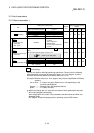
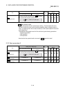
Pr.5
Pulse output mode
Set the pulse output mode to match the servo amplifier being used.
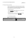
IMPORTANT
The only valid value of the "
Pr.5
Pulse output mode" is the value at the moment
when the PLC READY signal [Y0] turns from OFF to ON for the first time after the
power is switched ON or the PLC CPU is reset. Once the PLC READY signal [Y0]
has been turned ON, the value will not be reset even if another value is set to the
parameter and the PLC READY signal [Y0] is turned from OFF to ON.
Use "
Pr.23
Output signal logic selection" to choose between the positive logic
(pulse rising edge detection) and negative logic (pulse falling edge detection).
An example of the pulse output mode for positive and negative logic is shown
below.
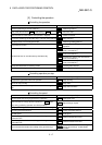
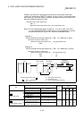
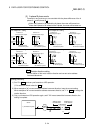
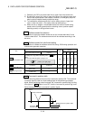
(1) PULSE/SIGN mode
Positive logic Negative logic
Forward run and reverse run are controlled with the ON/OFF
of the direction sign (SIGN).
•
The motor will forward run when the direction sign is HIGH.
•
The motor will reverse run when the direction sign is LOW.
Forward run and reverse run are controlled with the ON/OFF
of the direction sign (SIGN).
•
The motor will forward run when the direction sign is LOW.
•
The motor will reverse run when the direction sign is HIGH.
PULSE
SIGN
Forward
run
Reverse
run
Move in + direction Move in - direction
PULSE
SIGN
Forward
run
Reverse
run
Move in + direction Move in - direction
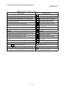
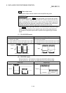
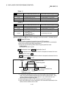
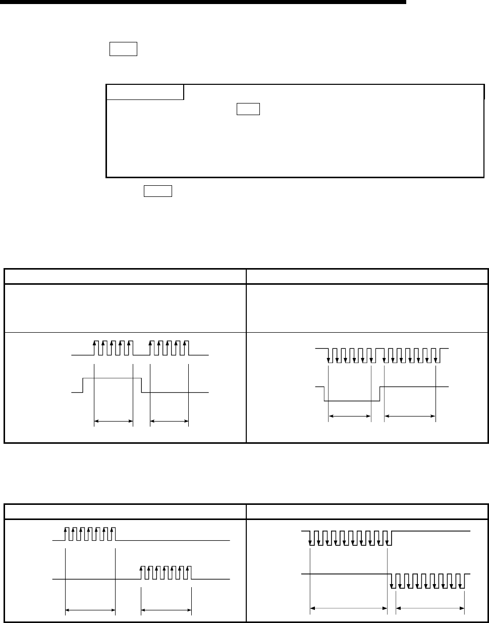
(2) CW/CCW mode
During forward run, the forward run feed pulse (PULSE F) will be output.
During reverse run, the reverse run feed pulse (PULSE R) will be output.
Positive logic Negative logic
PULSE F
PULSE R
Forward run Reverse run
PULSE F
PULSE R
Forward run Reverse run