


12 - 25
MELSEC-Q
12 CONTROL SUB FUNCTIONS
[4] Setting the torque limit function
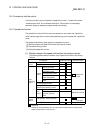
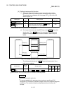
(1) To use the "torque limit function", set the "torque limit value" in the
parameters shown in the following table, and write them to the QD75.
The set details are validated at the rising edge (OFF
ON) of the PLC
READY signal (Y0).
Setting item
Setting
value
Setting details
Factory-set
initial value
Pr.17
Torque limit
setting value
Set the torque limit value as a percentage. 300
Pr.54
OPR torque limit
value
Set the torque limit value after the "
Pr.47
Creep
speed" is reached. Set as a percentage.
300
Refer to Section 5.2 "List of parameters" for setting details.
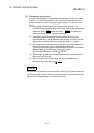
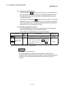
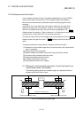
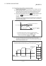
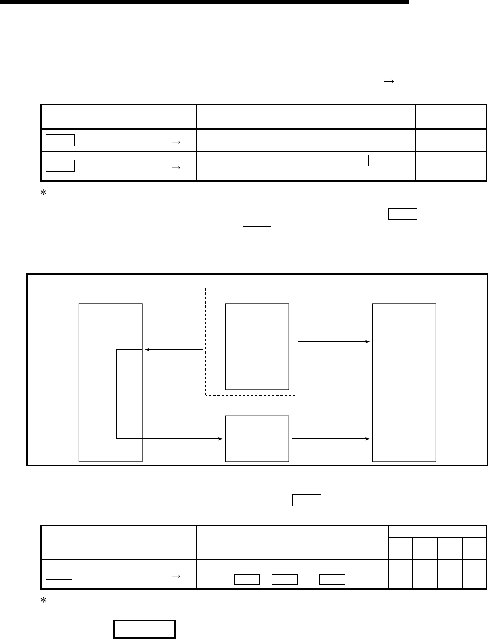
(2) The "torque limit value" set in the QD75 is set in the "
Md.35
Torque limit
stored value". The "
Md.35
Torque limit stored value" in the sequence
program is transferred to the "D/A converter module", and the torque is
limited.
PLC CPU
Buffer memory
Drive unit
Writing by a
TO command
Stored torque
limit value
826
D/A convertor module
Reading by a
FROM command
QD75
Torque limiting
Positioning control
Fig. 12.14 Limiting the torque to the drive unit (Axis 1)
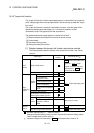
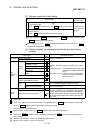
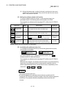
The following table shows the "
Md.35
Torque limit stored value" of the
buffer memory address.
Buffer memory address
Monitor item
Monitor
value
Storage details
Axis
1
Axis
2
Axis
3
Axis
4
Md.35
Torque limit stored
value
The "torque limit value" valid at that time is
stored. (
Pr.17
,
Pr.54
, or
Cd.22
)
826 926 1026 1126
Refer to Section 5.6 "List of monitor data" for information on the setting details.
REMARK
•
Parameters are set for each axis.
•
It is recommended that the parameters be set whenever possible with GX
Configurator-QP. Execution by sequence program uses many sequence programs
and devices. The execution becomes complicated, and the scan times will
increase.