


12 - 51
MELSEC-Q
12 CONTROL SUB FUNCTIONS
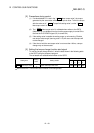
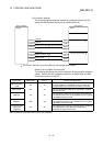
(2) Preparation
Prepare the absolute position detection system taking care of the following.
Component Details
1) Servo amplifier
• Install the battery to the servo amplifier.
• Validate the absolute position detection function of the
servo amplifier.
Refer to the servo amplifier manual for details.
2) Servomotor
• Use a servomotor with absolute position detector.
Refer to the servomotor manual for details.
3) Detector cable
• Add a battery power connection cable (BAT/LG signal) for
wiring the incremental detector cable.
Refer to the cable operation manual for details.
4) PLC system
• Carry out the transmission and receiving of the absolute
position detection data by the I/O modules (input 3
points/output 3 points).
• Use the "16 point input module" and "16 point output
module".
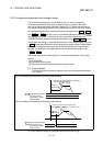
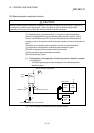
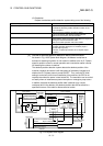
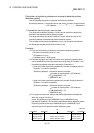
[2] Outline of absolute position detection data communication
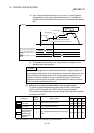
As shown in Fig. 12.33 System block diagram, the detector comprises an
encoder for detecting its position in one rotation in addition to the A, B, Z phase
signal for position control in normal operation and a cumulative rotation counter
for detecting the number of rotations.
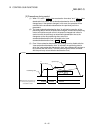
The absolute position detection system detects the absolute position of the
machine constantly and stores it with the backup of the battery irrespective of
whether the PLC system power is turned ON/OFF. Thus, once the OP initial
setting is carried out at the time of installation of the machine, the OPR is not
required even when the power is later turned ON. The restoration can be carried
out easily when an instantaneous power interruption or emergency stop occurs.
In addition, because the absolute position data is backed up by a super
condenser built in the detector, the absolute position data will be stored for a
specified time even if the cable is disconnected or broken.
I/O module
PLC system
Current feed value
Current
position
change
QD75QCPU
Output
Input
Servo amplifier
Position
control/
speed
control
Pulse train
command
OP data
Backup at
power OFF
LS0
1X0
1X
Detection of
position in one
rotation
LS
Speed
detection
Servomotor
Counter in one rotation
A.B.Z phase signal
Detector
1 pulse/rev cumulative rotation
counter
Super condenser
High-speed serial
communication
Battery
Current
position
Machine feed value
E PROM memory
2
Fig. 12.33 System block diagram