


12 - 69
MELSEC-Q
12 CONTROL SUB FUNCTIONS
[4] Setting the M code output function
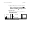
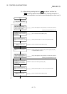
The following shows the settings to use the "M code output function".
(1) Set the M code No. in the positioning data "
Da.10
M code".
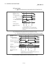
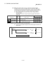
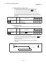
(2) Set the timing to output the M code ON signal (X4, X5, X6, X7).
Set the required value in the following parameter, and write it to the QD75.
The set details are validated at the rising edge (OFF
ON) of the PLC READY
signal (Y0).
Buffer memory address
Setting item
Setting
value
Setting details
Axis
1
Axis
2
Axis
3
Axis
4
Pr.18
M code ON signal
output timing
Set the timing to output the M code ON signal.
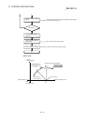
0: WITH mode
1: AFTER mode
27 177 327 477
Refer to Section 5.2 "List of parameters" for setting details.
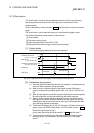
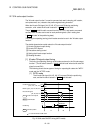
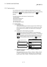
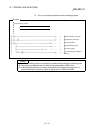
[5] Reading M codes
"M codes" are stored in the following buffer memory when the M code ON signal
turns ON.
Buffer memory address
Monitor item
Monitor
value
Storage details
Axis
1
Axis
2
Axis
3
Axis
4
Md.25
Valid M code
The M code No. (
Da.10
M code) set in the
positioning data is stored.
808 908 1008 1108
Refer to Section 5.6 "List of monitor data" for information on the storage details.
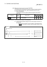
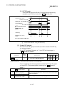
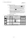
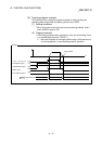
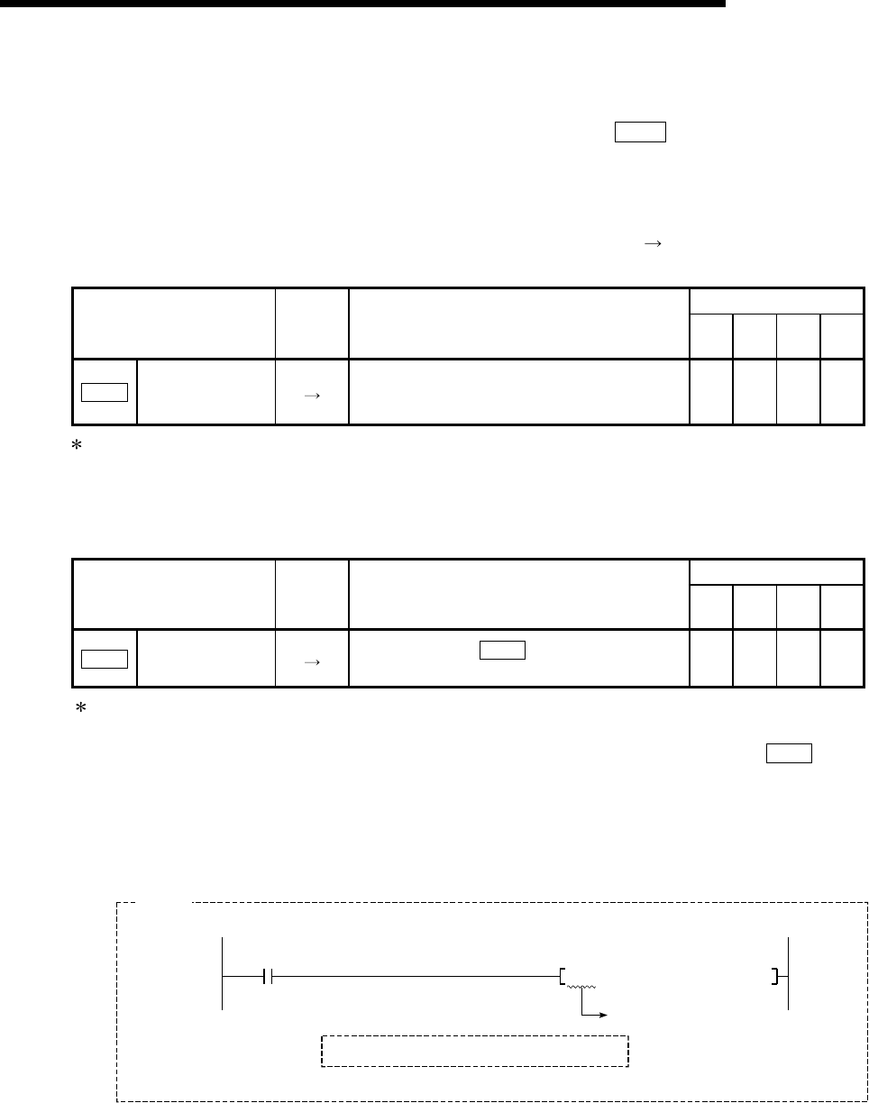
The following shows a sequence program example for reading the "
Md.25
Valid
M code" to the PLC CPU data register (D110). (The read value is used to
command the sub work.)
Read M codes not as "rising edge commands", but as "ON execution
commands".
M code ON signal
K1
D110
K808H0FROM
ON execution command
D110: valid M codes
Example