


8 - 11
MELSEC-Q
8 OPR CONTROL
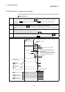
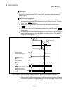
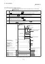
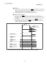
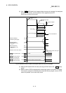
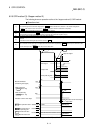
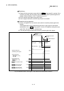
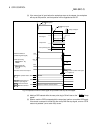
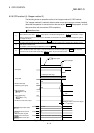
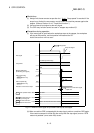
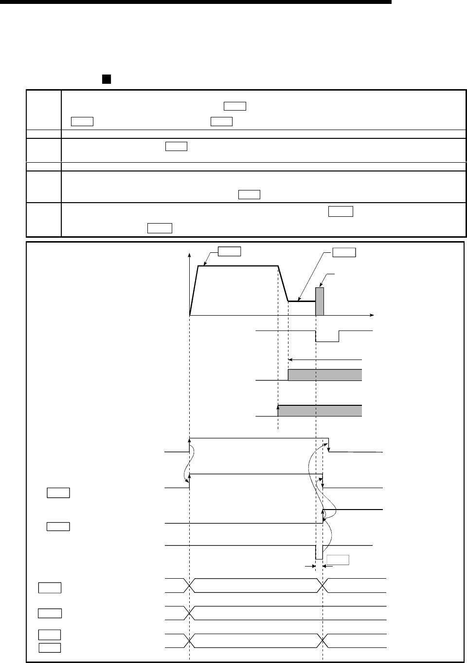
8.2.5 OPR method (3): Stopper method 2)
The following shows an operation outline of the "stopper method 2)" OPR method.
Operation chart
1)
The machine OPR is started.
(The machine begins the acceleration designated in "
Pr.51
OPR acceleration time selection", in the direction designated in
"
Pr.44
OPR direction". It then moves at the "
Pr.46
OPR speed" when the acceleration is completed.)
2) The machine begins decelerating when the near-point dog ON is detected.
3)
The machine decelerates to the "
Pr.47
Creep speed", and subsequently moves at that speed.
(Torque limiting is required at this time. If the torque is not limited, the servomotor may fail in step 4).)
4) The machine presses against the stopper at the creep speed and stops.
5)
The pulse output from the QD75 will stop at the zero signal after the machine stops, outputting the "deviation counter clear output" to the
drive unit.
(A "deviation counter clear signal output time" is set in the
Pr.55
.)
6)
After a "deviation counter clear output" is output to the drive unit, the OPR complete flag (
Md.31
Status: b4) turns from OFF to ON,
and the OPR request flag (
Md.31
Status: b3) turns from ON to OFF.
t
ON
OFF
ON
OFF
OFF
ON
0
V
ON
Zero signal
1)
2) 3) 4)
Pr. 46 OPR speed
Pr. 47 Creep speed
Stops at stopper
6)
5)
Valid torque limit range
Near-point dog OFF
Torque limit
Machine OPR start
(Positioning start signal)
Deviation counter clear output
Md.26 Axis operation status
Standing by
Inconsistent
Inconsistent
In OPR
Value the machine moved is stored
OPR request flag
[ Md.31 Status : b3]
OPR complete flag
[ Md.31 Status : b4]
Md.34 Movement amount
after near-point dog ON
Md.20 Current feed value
Md.21 Machine feed value
Standing by
OP address
Pr.55 Deviation counter clear signa
l
output time
Fig. 8.7 Stopper method 2) machine OPR