


3 - 20
MELSEC-Q
3 SPECIFICATIONS AND FUNCTIONS
3.4.3 List of input/output signal details
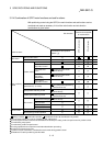
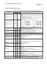
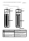
The details of each QD75 external device connection connector are shown below:
Pin No.
Signal name
AX1 AX2 AX3 AX4
Signal details
(Negative logic is selected by external I/O signal logic selection)
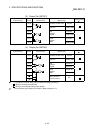
Manual pulse generator A
phase
Manual pulse generator B
phase
1A19
1A20
—
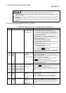
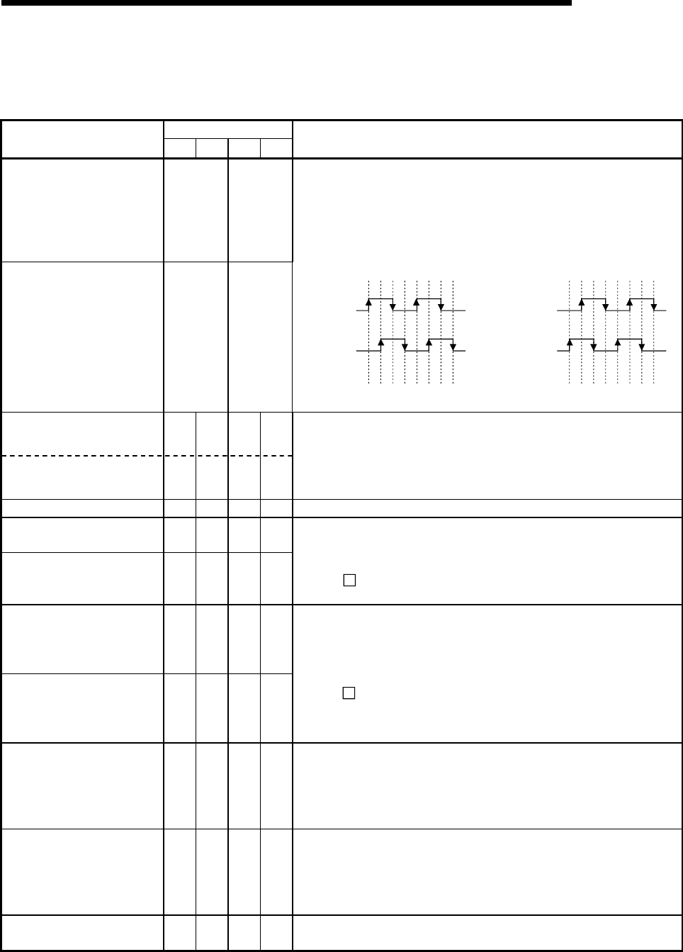
• Input the pulse signal from the manual pulse generator A phase and B
phase.
• If the A phase leads the B phase, the positioning address will increase at the
rising and falling edges of each phase.
• If the B phase leads the A phase, the positioning address will decrease at the
rising and falling edges of each phase.
[When increased] [When decreased]
Manual pulse generator A
common
Manual pulse generator B
common
1B19
1B20
—
+1+1+1+1+1+1+1+1 -1 -1 -1 -1 -1 -1 -1 -1
A phase
B phase
Positioning
address
A phase
B phase
Positioning
address
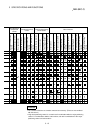
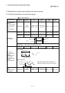
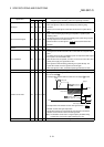
Zero signal (+24V) 1A8 1B8 2A8 2B8
Zero signal (+5V) 1A9 1B9 2A9 2B9
• Input the zero signal for machine OPR.
Use the pulse encoder's zero signal and so on.
• Also use this signal when the machine OPR method is the stopper method
and the OPR complete is input from an external source.
• The zero signal is detected at turning from OFF to ON.
Zero signal common 1A10 1B10 2A10 2B10 • Common for zero signal (+5V) and zero signal (+24V).
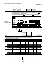
Pulse output F (+) <CW+>
Pulse output F (–) <CW–>
1A15
1A16
1B15
1B16
2A15
2A16
2B15
2B16
Pulse output R (+) <CCW+>
Pulse output R (–)
<CCW–>
1A17
1A18
1B17
1B18
2A17
2A18
2B17
2B18
• Output the positioning pulses and pulse sign for the differential driver output
system compatible drive unit.
(QD75D
only)
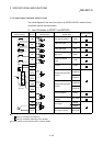
Pulse output F
<CW>
Pulse output F common
<CWCOM>
1A15
1A16
1B15
1B16
2A15
2A16
2B15
2B16
Pulse output R
<CCW>
Pulse output R common
<CCWCOM>
1A17
1A18
1B17
1B18
2A17
2A18
2B17
2B18
• Output the positioning pulses and pulse sign for the open collector output
system compatible drive unit.
(QD75P
only)
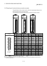
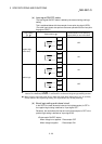
Upper limit signal 1A1 1B1 2A1 2B1
• This signal is input from the limit switch installed at the upper limit position of
the stroke.
• Positioning will stop when this signal turns OFF.
• When OPR retry function is valid, this will be the upper limit for finding the
near-point dog signal.
Lower limit signal 1A2 1B2 2A2 2B2
• This signal is input from the limit switch installed at the lower limit position of
the stroke.
• Positioning will stop when this signal turns OFF.
• When OPR retry function is valid, this will be the lower limit for finding the
near-point dog signal.
Near-point dog signal 1A3 1B3 2A3 2B3
• This signal is used for detecting the near-point dog during OPR.
• The near-point dog signal is detected at turning from OFF to ON.