


5 - 74
MELSEC-Q
5 DATA USED FOR POSITIONING CONTROL
5.4 List of block start data
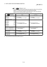
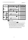
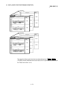
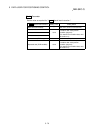
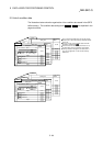
The illustrations below show the organization of the block start data stored in the QD75
buffer memory. The block start data setting items
Da.11
to
Da.14
are explained in
the pages that follow.
Setting item
Buffer memory
address
26049
26099
œˆÊ’uŒˆ‚ßn“®ƒf[ƒ^
26001
26051
b15 b0b7b8
Da.11 Shape
Da.12 Start data No.
26000
b15 b0b7b8
Da.13 Special start
instruction
Da.14 Parameter
26050
Buffer memory
address
Buffer memory
address
Setting item
Setting item
1st point
2nd point
50th point
Axis 1 (Start block 0)
27049
27099
27001
27051
œˆÊ’uŒˆ‚ßn“®ƒf[ƒ^
b15 b0b7b8
Da.11 Shape
Da.12 Start data No.
27000
b15 b0
b7
b8
Da.13 Special start
instruction
Da.14 Parameter
27050
Setting item
Buffer memory
address
Buffer memory
address
Buffer memory
address
Setting item
Setting item
1st point
2nd point
50th point
Axis 2 (Start block 0)
Up to 50 block start data points can be set
(stored) for each axis in the buffer memory
addresses shown on the left.
Items in a single unit of block start data are
shown included in a bold frame.
Each axis has five start blocks (block Nos.
0 to 4).
For information on the organization of the
buffer memory addresses assigned to the
start blocks 1 to 4, refer to Appendix 12
"List of buffer memory addresses".