


1 - 10
MELSEC-Q
1 PRODUCT OUTLINE
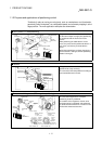
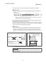
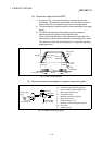
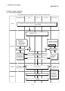
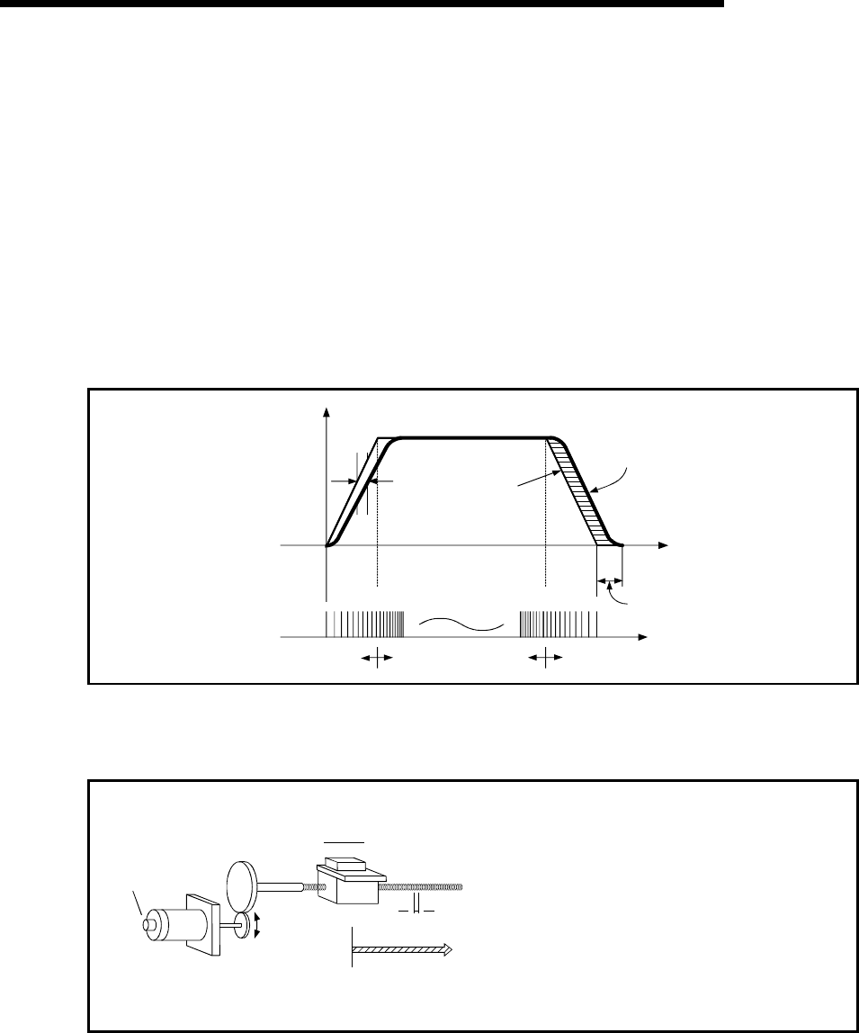
(b) Pulse train output from the QD75
1) As shown in Fig. 1.3, the pulse frequency increases as the motor
accelerates. The pulses are sparse when the motor starts and more
frequent when the motor speed comes close to the target speed.
2) The pulse frequency stabilizes when the motor speed equals the target
speed.
3) The QD75 decreases the pulse frequency (sparser pulses) to
decelerate the motor before it finally stops the output.
There will be a little difference in timing between the decrease in the
pulse frequency and the actual deceleration and stopping of the motor.
This difference, called "the stop settling time", is required for gaining a
stopping accuracy.
Speed V
Pulse droop
amount
Pulse
distribution
Servomotor
speed
Accel-
eration
Decel-
eration
Time t
Stop
settling time
Pulse train Rough Dense Rough
Fig. 1.3 QD75 output pulses
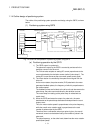
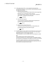
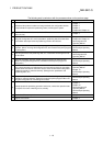
(2) Movement amount and speed in a system using worm gears
V
R
L
P0
P
Pulse encoder
(PLG)
Workpiece
Worm gear
Table
Servomotor
A : Movement amount per pulse (mm/pulse)
Vs : Command pulse frequency (pulse/s)
n : Pulse encoder resolution (pulse/rev)
L : Worm gear lead (mm/rev)
R : Deceleration ratio
V : Movable section speed (mm/s)
N : Motor speed (r/min)
K : Position loop gain (1/s)
ε
: Deviation counter droop pulse amount
P0 : OP (pulse)
P : Address (pulse)
Fig. 1.4 System using worm gears