


Appendix - 42
MELSEC-Q
APPENDICES
Appendix 7 Connection examples with servo amplifiers manufactured by SANYO DENKI
Co., Ltd.
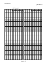
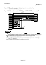
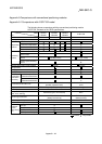
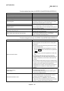
Appendix 7.1 Connection example of QD75D and PYO series (Differential driver)
4
PULSE F+
PULSE R+
CLEAR
CLEAR COM
READY
PULSER A+
PULSER A-
PULSER B+
PULSER B-
B19
A20
B20
DOG
FLS
RLS
STOP
CHG
COM
COM
3
1
2
4
5
15
16
17
18
14
8
24G
P24V
PYO
3
PPC
5V
A
B
0V
+5V
5G
2
2
1
PULSE F-
PULSE R-
RDY COM
10
PGO24
PGO COM
13
11
12
A19
6
7
PPC
NPC
NPC
CLE
SG
COP
SRDY
DOR-24V
NROT
26
27
28
29
34
25
11
41
49
SON
PROT
37
32
33
SG
24
SG
DC5-24V
13
50
QD75D
SG48
2m max
5
Manual pulse
generator
MR-HDP01
Differential driver
common terminal
Near-point dog
Upper limit 2
Lower limit 2
Stop
External command
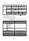
REMARK
(1)
1: The logic for each I/O terminal can be changed with "
Pr.22
Input signal logic selection" and "
Pr.23
Output
signal logic selection" in detailed parameters 1. (Negative logic is used for all terminals in the example above.)
(2)
2: The QD75D
upper limit (FLS) and lower limit (RLS) are used in the OPR retry function. Set these signals
inside the servo amplifier limit switches.
(3)
3: Refer to the manual of the servo amplifier for information on the servo amplifier side wiring and various signal
wire shields not shown above.
(4)
4: Use the same logic (positive logic/negative logic) for the QD75D
and servo amplifier. The QD75D
is
initially set to negative logic.
(5)
5: This indicates the distance between the QD75D
and PYO.