


Appendix - 59
MELSEC-Q
APPENDICES
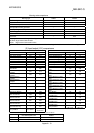
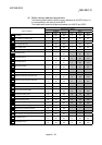
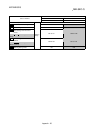
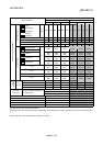
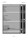
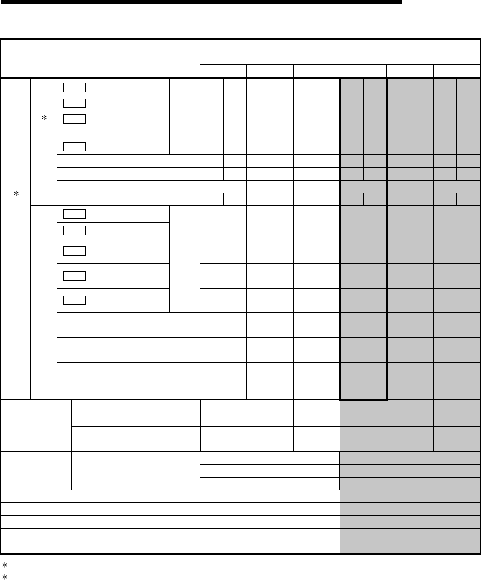
Buffer memory address
A1SD75 QD75
Items of A1SD75
Axis 1 Axis 2 Axis 3 Axis 1 Axis 2 Axis 3
Da.10
Shape
Da.11
Start data No.
Da.12
Special start
instruction
Da.13
Parameter
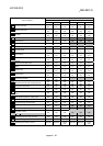
1st
point
4300 4350 4550 4600 4800 4850
26000 26050 27000 27050 28000 28050
2nd point 4301 4351 4551 4601 4801 4851
26001 26051 27001 27051 28001 28051
3rd point 4302 4352 4552 4602 4802 4852
26002 26052 27002 27052 28002 28052
to to to to to to to
Start block data 2
50th point 4349 4399 4599 4649 4849 4899
26049 26099 27049 27099 28049 28099
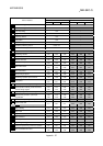
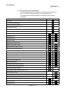
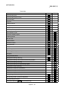
Da.14
Condition target
Da.15
Condition operator
4400 4650 4900
26100 27100 28100
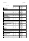
Da.16
Address
4402
4403
4652
4653
4902
4903
26102
26103
27102
27103
28102
28103
Da.17
Parameter 1
4404
4405
4654
4655
4904
4905
26104
26105
27104
27105
28104
28105
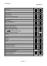
Da.18
Parameter 2
No. 1
4406
4407
4656
4657
4906
4907
26106
26107
27106
27107
28106
28107
No. 2
4410 to
4419
4660 to
4669
4910 to
4919
26110 to
26119
27110 to
27119
28110 to
28119
No. 3
4420 to
4429
4670 to
4679
4920 to
4929
26120 to
26129
27120 to
27129
28120 to
28129
to to to to to to to
Positioning start information 2
Condition data
No. 10
4490 to
4499
4740 to
4749
4990 to
4999
26190 to
26199
27190 to
27199
28190 to
28199
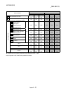
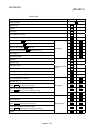
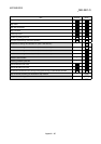
Start No. 8001 4500 4750 5000 – – –
Start No. 8002 4501 4751 5001 – – –
to to to to to to to
Positioning
start
information
Indirect
specification
Start No. 8050 4549 4799 5049 – – –
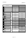
5050 30000
to to
PLC CPU
memo area
Condition judgment target data of
the condition data
5099
30099
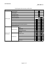
Target axis 5100 –
Head positioning block No. 5101 –
No. of read/write data items 5102 –
Read/write request 5103 –
Read/write block 5110 to 6109 –
2: With the QD75, it is called "block start data".
3: With the QD75, the "block start data" and "condition data" in the shaded area are called "start block 0". There are five start blocks: 0 to
4.
Refer to Appendix 12 "List of buffer memory addresses" for details.