


5 - 32
MELSEC-Q
5 DATA USED FOR POSITIONING CONTROL
An M code is a number between 0 and 65535 that can be assigned to each positioning
data (
Da.10
).
The sequence program can be coded to read an M code from the buffer memory
address specified by "
Md.25
Valid M code" whenever the M code ON signal [X4, X5,
X6, X7] turns ON so that a command for the sub work (e.g. clamping, drilling, tool
change) associated with the M code can be issued.
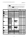
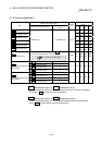
Setting value, setting range
Setting value buffer memory
address
Item
Value set with peripheral device
Value set with sequence
program
Default
value
Axis 1 Axis 2 Axis 3 Axis 4
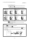
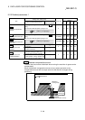
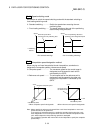
0 : Standard speed switching mode 0
Pr.19
Speed switching mode
1 : Front-loading speed switching
mode
1
0 28 178 328 478
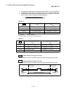
0 : Composite speed 0
Pr.20
Interpolation speed
designation method
1 : Reference axis speed 1
0 29 179 329 479
0 : Do not update current feed value 0
1 : Update current feed value 1
Pr.21
Current feed value during
speed control
2 : Clear current feed value to zero 2
0 30 180 330 480
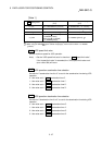
b0 Lower limit
b1 Upper limit
b2
Drive unit
READY
b3 Stop signal
b4
External
command
b5 Zero signal
b6
Near-point
signal
b7 Not used
b8
Manual pulse
generator input
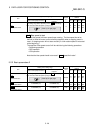
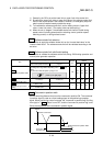
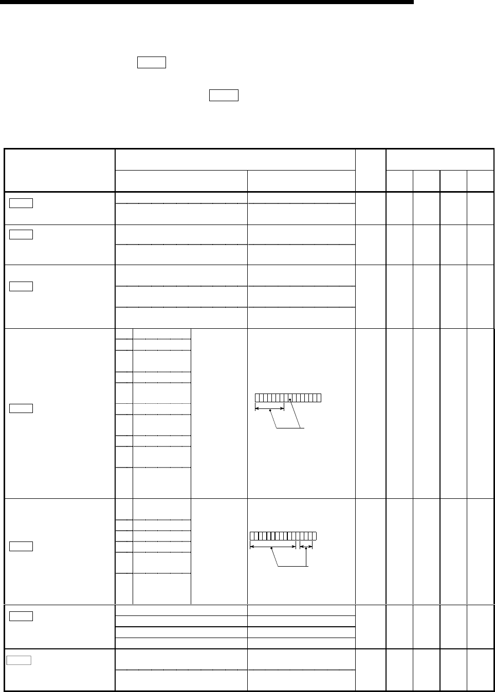
Pr.22
Input signal logic selection
b9
to
b15
Not used
0: Negative
logic
1: Positive
logic
b0123456789101112131415
Always "0" is set to
the
p
art not used.
0 31 181 331 481
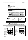
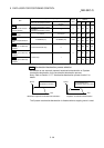
b0
Command
pulse signal
b1 Not used
b2 Not used
b3 Not used
b4
Deviation
counter clear
Pr.23
Output signal logic selection
b5
to
b15
Not used
0: Negative
logic
1: Positive
logic
b0123456789101112131415
Always "0" is set to
the
p
art not used.
0 32 182 332 482
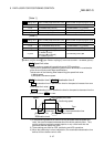
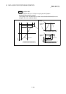
0: A-phase/B-phase multiplied by 4 0
1: A-phase/B-phase multiplied by 2 1
2: A-phase/B-phase multiplied by 1 2
Pr.24
Manual pulse generator
input selection
3: PULSE/SIGN 3
033–––
0: Speed-position switching control
(INC mode)
0
Pr.150
Speed-position function
selection
2: Speed-position switching control
(ABS mode)
2
0 34 184 334 484