


3 - 23
MELSEC-Q
3 SPECIFICATIONS AND FUNCTIONS
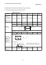
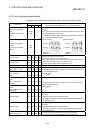
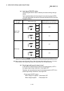
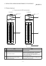
(a) Input signal ON/OFF status
The input signal ON/OFF status is defied by the external wiring and logic
setting.
This is explained below with the example of near-point dog signal (DOG).
(The other input signals also perform the same operations as the near-point
dog signal (DOG).)
Logic setting
3, 4
External wiring
4
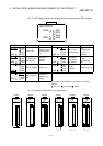
ON/OFF status of near-point dog
signal (DOG) as seen from QD75
(Voltage not applied)
DOG
COM
24VDC
OFF
Negative logic
(Initial value)
(Voltage applied)
DOG
COM
24VDC
ON
(Voltage not applied)
DOG
COM
24VDC
ON
Positive logic
(Voltage applied)
DOG
COM
24VDC
OFF
3: Set the logic setting using "
Pr.22
Input signal logic selection". For details of the settings, refer to
"Section 5.2.3 Detailed parameters 1" and "Section 13.4 External I/O signal logic switching function".
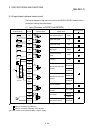
4: When using the upper limit signal (FLS) or lower limit signal (RLS), always wire it as a "b" (normally
closed) contact in the negative logic setting. The signal will turn OFF to stop positioning.
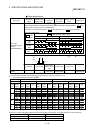
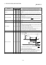
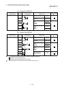
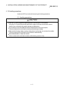
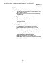
(b) About logic setting and internal circuit
In the QD75, the case where the internal circuit (photocoupler) is OFF in
the negative logic setting is defined as "input signal OFF".
Reversely, the case where the internal circuit (photocoupler) is OFF in the
positive logic setting is defined as "input signal ON".
<Photocoupler ON/OFF status>
When voltage is not applied : Photocoupler OFF
When voltage is applied : Photocoupler ON