


11 - 17
MELSEC-Q
11 MANUAL CONTROL
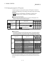
11.3 Inching operation
11.3.1 Outline of inching operation
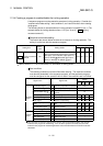
Important
When the inching operation is carried out near the upper or lower limit, use the
hardware stroke limit function (Refer to Section 12.4.4).
If the hardware stroke limit function is not used, the workpiece may exceed the
movement range, and an accident may result.
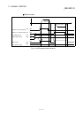
Inching operation
In inching operation, pulses are input to the drive unit at the first control cycle (1.8
ms) to move the workpiece by a designated movement amount after the forward
run JOG start signal [Y8, YA, YC, YE] or reverse JOG start signal [Y9, YB, YD, YF]
is turned ON.
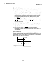
The following shows the example of inching operation.
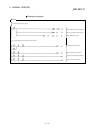
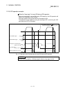
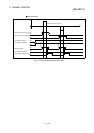
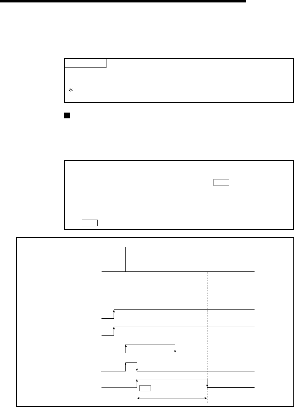
1)
When the start signal is turned ON, inching operation is carried out in the direction
designated by the start signal. In this case, BUSY signal is turned from OFF to ON.
2)
The workpiece is moved by a movement amount set in "
Cd.16
Inching movement
amount".
3)
The workpiece movement stops when the speed becomes "0". In this case, BUSY signal
is turned from ON to OFF. The positioning complete signal is turned from OFF to ON.
4)
The positioning complete signal is turned from ON to OFF after a time set in
"
Pr.40
Positioning complete signal output time" has been elapsed.
PLC READY signal [Y0]
OFF
ON
BUSY signal
[XC,XD,XE,XF]
OFF
OFF
ON
Positioning complete
signal
[X14,X15,X16,X17]
OFF
ON
Forward run inching operation
ON
OFF
QD75 READY signal
[X0]
Forward run JOG start
signal
[Y8,YA,YC,YE]
1)
2)
3) 4)
Positioning complete signal
output time
Pr.40
ON
Fig. 11.12 Inching operation