


3 - 21
MELSEC-Q
3 SPECIFICATIONS AND FUNCTIONS
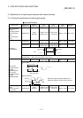
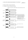
Pin No.
Signal name
AX1 AX2 AX3 AX4
Signal details
(Negative logic is selected by external I/O signal logic selection)
Stop signal 1A4 1B4 2A4 2B4
• Input this signal to stop positioning.
• When this signal turns ON, the QD75 will stop the positioning being
executed.
After that, even if this signal is turned from ON to OFF, the system will not
start.
External command signal 1A5 1B5 2A5 2B5
• Input a control switching signal during speed-position or position-speed
switching control.
• Use this signal as the input signal of positioning start, speed change request,
and skip request from an external source.
Set the function to use this signal in "
Pr.42
External command function
selection".
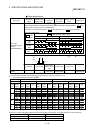
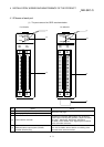
Common
1A6
1A7
1B6
1B7
2A6
2A7
2B6
2B7
• Common for upper/lower limit, near-point dog, stop, and external command
signals.
Drive unit READY 1A11 1B11 2A11 2B11
• This signal turns ON when the drive unit is normal and can accept the feed
pulse.
• The QD75 checks the drive unit READY signal, and outputs the OPR request
if the system is not in the READY state.
• When the drive unit is inoperable, such as if an error occurs in the drive unit's
control power supply, this signal will turn OFF.
• If this signal is turned OFF during positioning, the system will stop. The
system will not start even if this signal is turned ON again.
• When this signal turns OFF, the OPR complete signal will also turn OFF.
Drive unit READY common 1A12 1B12 2A12 2B12 • Common for drive unit READY signal.
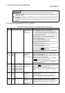
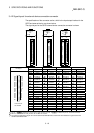
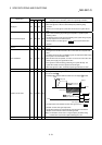
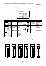
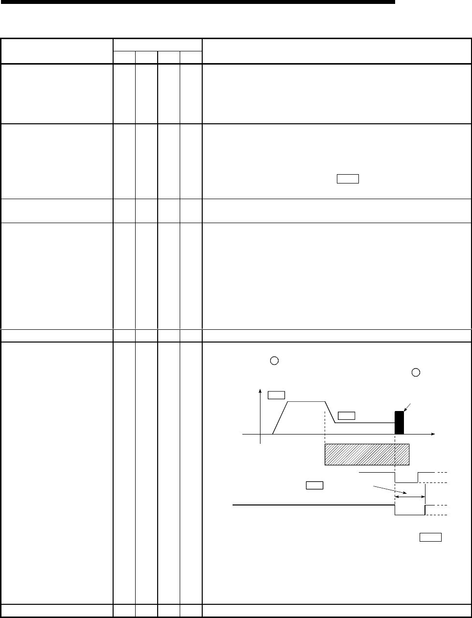
Deviation counter clear 1A13 1B13 2A13 2B13
• This signal is output during machine OPR. (Note that it is not output during
the count method
2
.)
(Example) When machine OPR is carried out in the stopper
2
method.
Pr.46
Creep speed
Near-point dog
Zero signal
Time
Speed
CLEAR
After feed pulse output stops
Stopper
Pr.47
Pr.55
Deviation counter
clear signal output time
OPR speed
OFF
ON
OFF
ON
• The output time of the deviation counter clear signal is set in "
Pr.55
Deviation counter clear signal output time".
• Use the drive unit that can reset the droop pulse amount in the internal
deviation counter when the QD75 turns this signal ON.
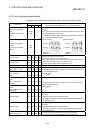
(Note) The deviation counter clear is a signal output by the QD75 during
machine OPR. It cannot be output randomly by the user.
Deviation counter clear common 1A14 1B14 2A14 2B14 • Common for deviation counter clear signal