


Appendix - 38
MELSEC-Q
APPENDICES
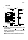
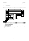
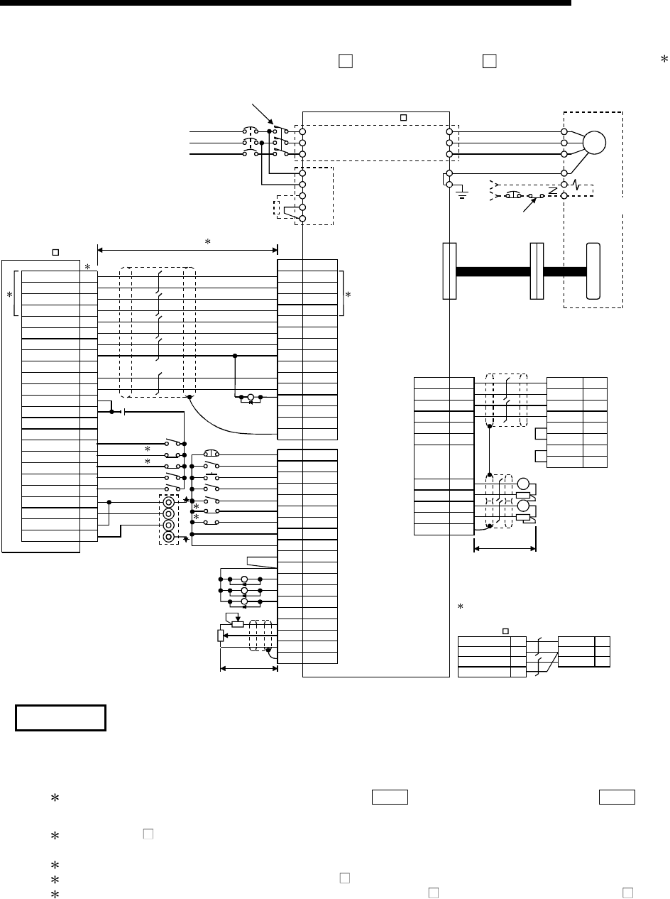
Appendix 4.2 Connection example of QD75D and MR-J2/J2S- A (Differential driver)
5
PULSE F+
15
PULSE F-
16
PULSE R+
17
PULSE R-
18
CLEAR
13
CLEAR COM 14
READY 11
RDY COM
12
PG05
9
PG0 COM
10
COM
6
COM
7
DOG
3
FLS
1
2
4
5
A19
RLS
STOP
CHG
PULSER A+
PULSER A-
PULSER B+
PULSER B-
B19
A20
B20
QD75D
EMG 15
SON
RES
PC
TL
LSP
LSN
SG
SG
VDD
COM
ALM
ZSP
TLC
P15R
TLA
LG
SD
5
14
8
9
16
17
10
20
3
13
18
19
6
11
12
1
Plate
OPC
PP
PG
NP
NG
CR
SG
RD
COM
LZ
LZR
LG
SD
11
3
13
2
12
8
10
19
9
5
15
1
Plate
5V
A
B
0V
5V
Manual pulse generator
MR-HDP01
5G
3
3
RA1
RA2
RA3
Fault
Zero speed detection
During torque limiting
Analog torque limit
+10V/max. current
1
CN1A
NF MC
L1
L2
L3
L11
L21
C TE2
D
P
CN1B
U
V
W
PE
PE
U
V
W
E
SM
B1
B2
EMG
24VDC
Cutoff by servo ON signal
OFF alarm signal.
HC-MF, HA-FF
series motor
Detector
CN2
MR-J2/MR-J2S- A
TE1
12
2
1
11
5
15
TxD
CN3
RxD
LG
LG
LG
LG
4MO1
3LG
14 MO2
13 LG
Plate
SD
RD
SD
GND
GND
RS
CS
DR
ER
Commercially
available
personal computer
A
A
Monitor output
10k
10k
Max. 1mA total
Two-way deviation
24VDC
Configure a sequence to turn OFF the
MC at alarms and emergency stops.
Power supply
3-phase 200VAC
Within 10m 4
Near-point dog
Upper limit 2
Lower limit 2
Stop
External command
Servo ON
Reset
Torque limit
Forward run stroke end
Reverse run stroke end
External
emergency stop
Proportional control
Within 2m
Electromagnetic
brake
Within 2m
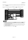
15
16
PULSE F
PULSE COM
PULSE R
PULSE COM
17
18
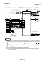
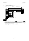
QD75P
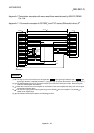
When connecting an open collector,
make connection as shown below.
3
10
PP
SG
NP
2
CN1
Positioning
complete
RA4
INP 18
REMARK
(1)
It is recommended to make differential driver connection since differential driver connection is more excellent than
open collector connection in max. output pulse and max. connection distance between servos. (Refer to Section
3.1 "Performance specifications".)
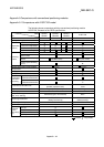
(2)
1: The logic for each I/O terminal can be changed with "
Pr.22
Input signal logic selection" and "
Pr.23
Output
signal logic selection" in detailed parameters 1. (Negative logic is used for all terminals in the example above.)
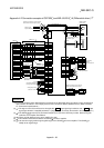
(3)
2: The QD75D
upper limit (FLS) and lower limit (RLS) are used in the OPR retry function. Set these signals
inside the servo amplifier limit switches.
(4)
3: These are limit switches for the servo amplifier (for stop).
(5)
4: This indicates the distance between the QD75D
and servo amplifier.
(6)
5: Use the same logic (positive logic/negative logic) for the QD75D
and servo amplifier. The QD75D
is
initially set to negative logic.