


Appendix - 47
MELSEC-Q
APPENDICES
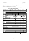
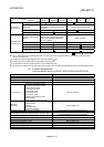
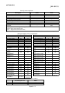
Model
Item
QD75P1
QD75D1
QD75P2
QD75D2
QD75P4
QD75D4
A1SD75P1
-S3
A1SD75P2
-S3
A1SD75P3
-S3
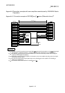
STRT signal
(integrated into "CHG")
(External start signal)
CHG signal
External command signal (External start or
speed-position switching selectable with
parameters)
Speed-position switching signal
In-position (INP)
(for monitor)
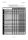
I/O signal for
external devices
Signal logic switching
Command pulse output signal only
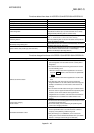
Connection with peripheral
devices
Connection via PLC CPU,
Q Corresponding Serial Communication
Module, Q Corresponding MELSEC/H
Remote I/O Module
Direct connection
AD71TU
AD75TU
A6GPP, A6PHP
Peripheral devices
(data setting, etc.)
DOS/V personal computer
: Possible, : Not possible
1: Up to 100 data items/axis of positioning data (No. 1 to 100) can be set using the buffer memory. The positioning data in the buffer
memory is not backed up.
2: Indicates the standard mode/stepping motor mode about A1SD75P -S3.
3: Indicates the INC mode/ABS mode in speed-position switching control.
4: The deviation counter clear signal output time can be set with parameters.
5: The near pass function is valid only during the continuous path control. (A1SD75: Selected with parameters, QD75: Standard function)
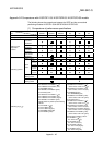
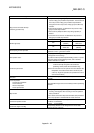
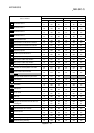
(2) Function comparisons
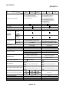
Functions added to those of A1SD75P1-S3/A1SD75P2-S3/A1SD75P3-S3
Added functions Remarks
External I/O signal logic switching function Refer to Section 13.4.
Inching operation Refer to Section 11.3.
Target position change function Refer to Section 12.7.5.
Multiple axes simultaneous start control Refer to Section 10.5.
Control systems
3-axis linear interpolation control
4-axis linear interpolation control
3-axis fixed-feed control
4-axis fixed-feed control
2-axis speed control
3-axis speed control
4-axis speed control
Position-speed switching control
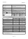
NOP instruction
LOOP instruction, LEND instruction
Refer to Chapter 9.
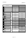
Dedicated
instructions
Absolute position restoration
Positioning start
Teaching
Flash ROM writing
Parameter initialization
Refer to Chapter 14.
Automatic refresh of intelligent function modules Refer to GX Configurator-QP Operating Manual.
Output hold/clear parameter setting during PLC CPU error stop
Refer to QCPU User's Manual
(Function Explanation, Program Fundamentals).
Flash ROM write limit Refer to Section 13.3.
Speed-position switching control (ABS mode) Refer to Section 9.2.7.
Pre-reading start function Refer to Section 12.7.8.
External I/O signal monitor function Refer to Section 13.5.
Multiple PLC compatible function Refer to QCPU User's Manual (Multiple CPU System).
Deceleration start flag function Refer to Section 12.7.9
Stop command processing for deceleration stop function Refer to Section 12.7.10