


12 - 29
MELSEC-Q
12 CONTROL SUB FUNCTIONS
[4] Precautions during software stroke limit check
(1) A machine OPR must be executed beforehand for the "software stroke limit
function" to function properly.
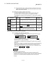
(2) During interpolation control, a stroke limit check is carried out for the every
current value of both the reference axis and the interpolation axis. Every
axis will not start if an error occurs, even if it only occurs in one axis.
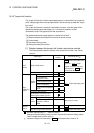
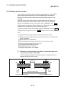
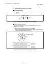
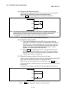
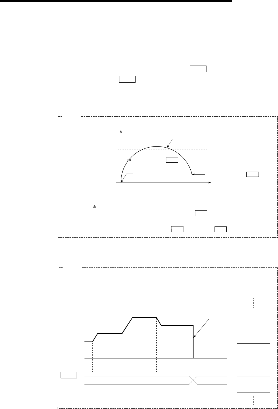
(3) During circular interpolation control, the "
Pr.12
Software stroke limit upper
limit value"/"
Pr.13
Software stroke limit lower limit value" may be
exceeded.
In this case, a deceleration stop will not be carried out even if the stroke limit
is exceeded. Always install an external limit switch if there is a possibility the
stroke limit will be exceeded.
Arc address ( Da. 7 )
End point address ( Da. 6 )
Axis 1
Axis 1 stroke limit
Deceleration stop not carried out
Starting address
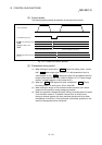
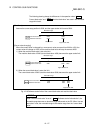
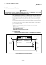
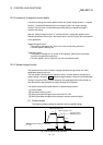
The software stroke limit check is carried out for the following addresses
during circular interpolation control. (Note that " Da. 7 Arc address" is carried
out only for circular interpolation control with sub point designation.
Current value/end point address ( Da. 6 )/arc address ( Da. 7 )
Axis 2
Example
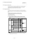
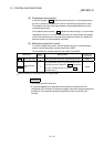
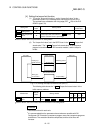
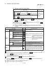
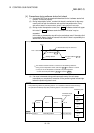
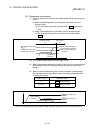
(4) If an error is detected during continuous path control, the axis stops
immediately on completion of execution of the positioning data located right
before the positioning data in error.
Md. 26
Axis operation status
No.10 No.11 No.12 No.13
Immediate stop at
error detection
No.10
P11
No.11
P11
No.12
P11
No.13
P11
No.14
P01
Controlling position
Error occurring
Positioning data
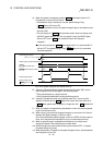
• If the positioning address of positioning data No. 13 is outside the software stroke limit range,
the operation immediately stops after positioning data No. 12 has been executed.
Example