


12 - 79
MELSEC-Q
12 CONTROL SUB FUNCTIONS
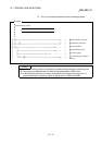
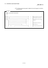
[3] Method of setting target position change function from PLC CPU
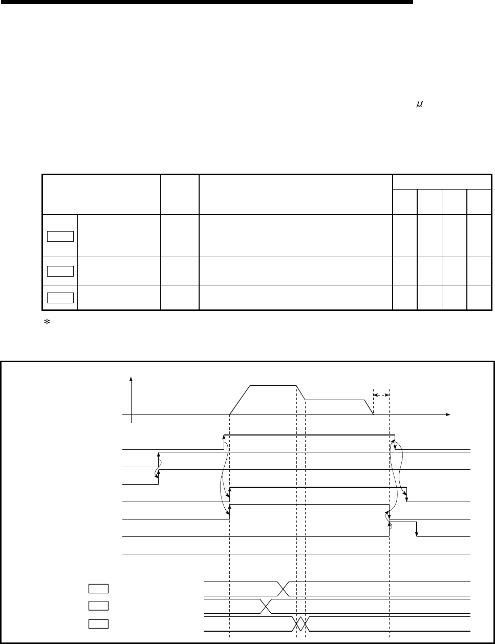
The following table and chart show the example of a data setting and sequence
program used to change the target position of the axis 1 by the command from
the PLC CPU, respectively. (example in which the target position value and
command speed are changed to a new target position of "300.0
m" and a new
command speed of "10000.00 mm/min".)
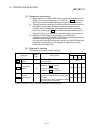
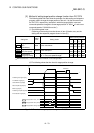
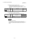
(1) The following data is set.
(Referring to the starting time chart shown in item (2) below, carry out the
setting with the sequence program shown in item (3).)
Buffer memory address
Setting item
Setting
value
Setting details
Axis
1
Axis
2
Axis
3
Axis
4
Cd.27
Target position
value
(new address)
3000 Set the new address.
1534
1535
1634
1635
1734
1735
1834
1835
Cd.28
Target position
value (new speed)
1000000 Set the new speed.
1536
1537
1636
1637
1736
1737
1836
1837
Cd.29
Target position
change request flag
1
Set "1: Carry out speed change".
1538 1638 1738 1838
Refer to Section 5.7 "List of control data" for details on the setting details.
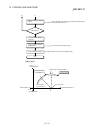
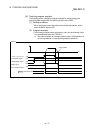
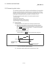
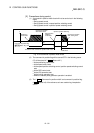
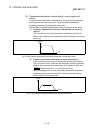
(2) The following shows the time chart for target position change.
PLC READY signal [Y0]
QD75 READY signal [X0]
Start complete signal [X10]
BUSY signal [XC]
Error detection signal [X8]
V
t
Positioning start signal [Y10]
Target position value (new address)
Target position value (new speed)
1000000
3000
Positioning complete signal [X14]
Dwell time
Cd.27
Cd.28
Target position change request flag
1
0
0
Cd.29
Fig. 12.42 Time chart for target position change from PLC CPU