


3 - 17
MELSEC-Q
3 SPECIFICATIONS AND FUNCTIONS
3.4 Specifications of input/output interfaces with external devices
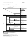
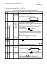
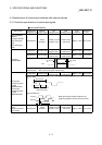
3.4.1 Electrical specifications of input/output signals
Input specifications
Signal name
Rated input
voltage/current
Working
voltage range
ON
voltage/current
OFF
voltage/current
Input
resistance
Response
time
Drive unit READY
(READY)
Stop signal (STOP)
Upper limit signal
(FLS)
Lower limit signal
(RLS)
24VDC/5mA
19.2 to
26.4VDC
17.5VDC or more/
3.5mA or more
7VDC or less/
1.7mA or less
Approx. 4.7k
Ω
4ms or less
5VDC/5mA 4.5 to 6.1VDC
2VDC or more/
2mA or more
0.5VDC or less/
0.5mA or less
Approx. 0.3k
Ω
1ms or less
24VDC/5mA 12 to 26.4VDC
10VDC or more/
3mA or more
3VDC or less/
0.2mA or less
Approx. 4.7k
Ω
1ms or less
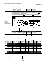
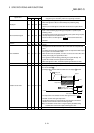
3 s or les
s
1ms or more
3 s or less
ON
OFF
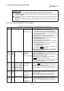
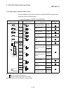
Zero signal
(PG05/PG024)
Differential receiver equivalent to Am26LS32
(ON/OFF level ON: 1.8V or more, OFF: 0.6V or less)
5VDC/5mA 4.5 to 6.1VDC
2.5VDC or more/
2mA or more
1VDC or less/
0.1mA or less
Approx. 1.5k
Ω
1ms or less
1
Pulse width
4ms or more
2ms or more
2ms
or more
(Duty ratio: 50%)
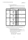
2
Phase difference
Manual pulse
generator A phase
(PULSE
GENERATOR A)
Manual pulse
generator B phase
(PULSE
GENERATOR B)
A phase
B phase
1ms or more
When the A phase leads the B phase, the
positioning address (current value) increases.
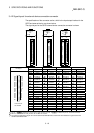
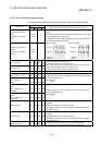
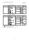
Near-point dog signal
(DOG)
External command
signal (CHG)
24VDC/5mA
19.2 to
26.4VDC
17.5VDC or more/
3.5mA or more
7VDC or less/
1.7mA or less
Approx. 4.3k
Ω
1ms or less