


Appendix - 60
MELSEC-Q
APPENDICES
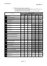
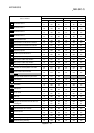
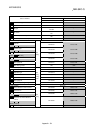
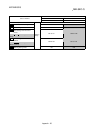
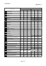
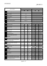
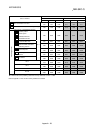
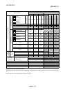
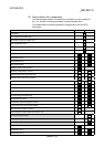
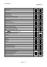
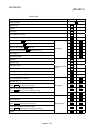
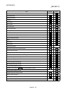
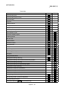
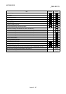
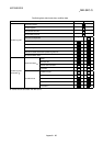
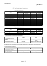
(5) Data indication No. comparisons
The following table shows the comparisons of numbers for each symbols (Pr.,
Md., Cd., and Da.) indicating parameters or positioning data items.
The shaded sections indicate the added or changed items with the QD75.
Parameters
Item A1SD75 QD75
Unit setting
Pr.1
No. of pulses per rotation (Ap)
Pr.2
Movement amount per rotation (Al)
Pr.3
Unit magnification (Am)
Pr.4
Pulse output mode
Pr.5
Rotation direction setting
Pr.6
Speed limit value
Pr.7 Pr.8
Acceleration time 0
Pr.8 Pr.9
Deceleration time 0
Pr.9 Pr.10
Bias speed at start
Pr.10 Pr.7
Stepping motor mode selection
Pr.11
–
Backlash compensation amount
Pr.12 Pr.11
Software stroke limit upper limit value
Pr.13 Pr.12
Software stroke limit lower limit value
Pr.14 Pr.13
Software stroke limit selection
Pr.15 Pr.14
Software stroke limit valid/invalid setting
Pr.16 Pr.15
Command in-position width
Pr.17 Pr.16
Torque limit setting value
Pr.18 Pr.17
M code ON signal output timing
Pr.19 Pr.18
Speed switching mode
Pr.20 Pr.19
Interpolation speed designation method
Pr.21 Pr.20
Current feed value during speed control
Pr.22 Pr.21
Manual pulse generator selection
Pr.23
–
Logic selection for pulse output to the drive unit
Pr.24
–
Input signal logic selection –
Pr.22
Output signal logic selection –
Pr.23
Manual pulse generator input selection –
Pr.24
Size selection for acceleration/deceleration time
Pr.25
–
Acceleration time 1
Pr.26 Pr.25
Acceleration time 2
Pr.27 Pr.26