


6 - 40
MELSEC-Q
6 SEQUENCE PROGRAM USED FOR POSITIONING CONTROL
REMARK
Restarting after stopping is possible even for the following control.
•
Incremental system position control
•
Continuous positioning control
•
Continuous path control
•
Block start
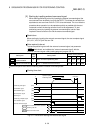
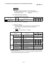
[3] Control data requiring setting
Set the following data to execute restart.
Buffer memory address
Setting item
Setting
value
Setting details
Axis 1 Axis 2 Axis 3 Axis 4
Cd.6
Restart command 1 Set "1: Restarts". 1503 1603 1703 1803
Refer to Section 5.7 "List of control data" for details on the setting details.
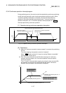
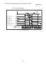
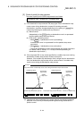
[4] Starting conditions
The following conditions must be satisfied when restarting. (Assemble the
required conditions into the sequence program as an interlock.)
(1) Operation state
"
Md.26
Axis operation status" is "1: Stopped"
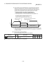
(2) Signal state
Device
Signal name Signal state
Axis 1 Axis 2
Axis 3
Axis 4
PLC READY signal ON PLC CPU preparation completed Y0
QD75 READY signal ON QD75 preparation completed X0
Synchronization flag ON
QD75 buffer memory
Accessible
X1
Axis stop signal OFF Axis stop signal is OFF Y4 Y5 Y6 Y7
M code ON signal OFF M code ON signal is OFF X4 X5 X6 X7
Error detection signal OFF No error is present X8 X9 XA XB
BUSY signal OFF BUSY signal is OFF XC XD XE XF
Interface
signal
Start complete signal OFF Start complete signal is OFF X10 X11 X12 X13
Drive unit READY signal ON Drive unit preparation completed –
Stop signal OFF Stop signal is OFF –
Upper limit (FLS) ON Within limit range –
External
signal
Lower limit (RLS) ON Within limit range –
: When the synchronous setting of the PLC CPU is made in the nonsynchronous mode, this must be
provided as an interlock.
When it is made in the synchronous mode, no interlock must be provided in the program because the
flag is turned ON when calculation is run on the PLC CPU.