


9 - 66
MELSEC-Q
9 MAJOR POSITIONING CONTROL
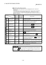
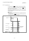
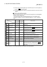
Positioning data setting examples
[Reference axis and interpolation axis are designated as axis 1 and axis 2,
respectively.]
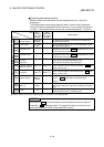
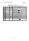
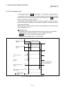
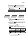
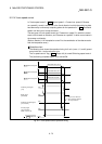
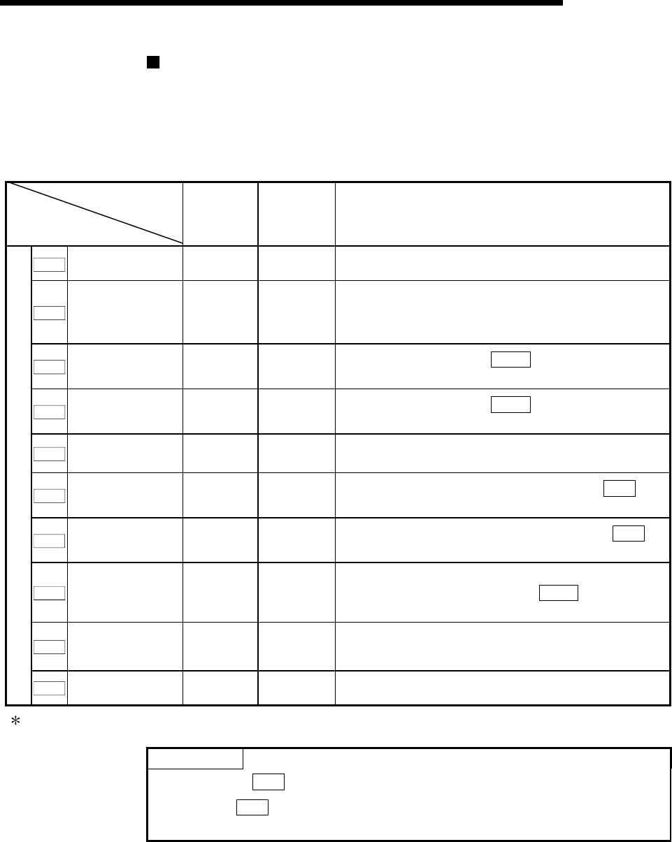
The following table shows setting examples when "2-axis circular interpolation
control with center point designation (INC circular right, INC circular left)" is set in
positioning data No. 1 of axis 1. (The required values are also set in positioning
data No. 1 of axis 2.)
Axis
Setting item
Axis 1
(reference
axis) setting
example
Axis 2
(interpolation
axis) setting
example
Setting details
Da.1
Operation pattern
Positioning
complete
–
Set "Positioning complete" assuming the next positioning
data will not be executed.
Da.2
Control system
INC circular
right
INC circular
left
–
Set incremental system, 2-axis circular interpolation control
with center point designation. (Select clockwise or
counterclockwise according to the control.)
Da.3
Acceleration time
No.
1–
Designate the value set in "
Pr.25
Acceleration time 1" as
the acceleration time at start.
Da.4
Deceleration time
No.
0–
Designate the value set in "
Pr.10
Deceleration time 0" as
the deceleration time at deceleration.
Da.5
Axis to be
interpolated
1–
Set the axis to be interpolated (partner axis).
If the self-axis is set, an error will occur.
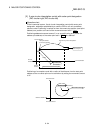
Da.6
Positioning address/
movement amount
8000.0
µ
m 6000.0
µ
m
Set the movement amount. (Assuming that the "
Pr.1
Unit
setting" is set to "mm".)
Da.7
Arc address
4000.0
µ
m 3000.0
µ
m
Set the center point address. (Assuming that the "
Pr.1
Unit setting" is set to "mm".)
Da.8
Command speed
6000.00
mm/min
–
Set the speed when moving to the end point address.
(Designate the composite speed in "
Pr.20
Interpolation
speed designation method".)
Da.9
Dwell time 500ms –
Set the time the machine dwells after the positioning stop
(pulse output stop) to the output of the positioning complete
signal.
Axis 1 Positioning data No. 1
Da.10
M code 10 –
Set this when other sub operation commands are issued in
combination with the No. 1 positioning data.
Refer to Section 5.3 "List of positioning data" for information on the setting details.
POINT
Set a value in "
Da.8
Command speed" so that the speed of each axis does not
exceed the "
Pr.8
Speed limit value". (The speed limit does not function for the
speed calculated by the QD75 during interpolation control.)