


Appendix - 83
MELSEC-Q
APPENDICES
OPR REQUEST
This signal turns ON when there is an error
with the QD75. It will turn ON in the following
situations.
1) When the power is turned ON.
2) When the PLC READY signal turns from
OFF to ON.
3) When the machine OPR starts.
4) When the drive unit READY signal turns
from ON to OFF.
The user judges whether to carry out a
machine OPR in the above situations.
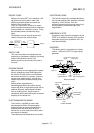
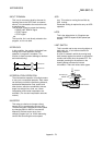
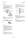
OUTPUT TERMINAL
This is a pin connector for outputting data from
the QD75 to an external source. It is
connected to the motor drive unit.
This terminal is used to output the following.
•
Feedback pulses for both forward run and
reverse run
•
Start
•
Deviation counter clear
The terminal Nos. are determined for each
axis.
The output No. Yn is not directly related to the
program, so it is not used.
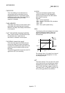
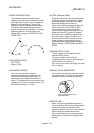
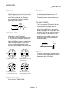
OVERRIDE FUNCTION
With this function, the speed during positioning
operations (current speed) can be varied
between 1 and 300%.
The speed can also be changed by the same
variable rate for continuous positioning with
differing designated speeds.
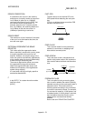
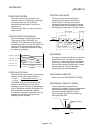
P RATE (Pulse Rate)
A coefficient that magnifies the feedback
pulses per motor shaft rotation by 2-fold, 3-
fold, 1/2 or 1/3.
It is the ratio of the feed pulses and feedback
pulses.
For example, when the No. of pulses per
motor shaft rotation is set to 2400 pulses, and
the P rate is set to 2, the result will be
equivalent to 1200 pulses.
The rotation per pulse is 0.15
°
when 2400
pulses per rotation are set, but this becomes
0.3
°
when 1200 pulses. The positioning
accuracy drops as the P rate is increased.
PARAMETER
This is the basic data used in positioning.
Parameters are determined by the machine
side design, so subsequent changes of
parameters must be accompanied by changes
in the machine design.
Data cannot be written during positioning. The
initial parameter values are written by the
maker.
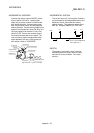
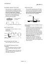
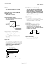
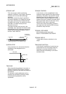
PG0 (Pulse Generator Zero)
Pronounced "pee-jee-zero". Refer to the term
"ZERO SIGNAL".
PG0
Feedback
pulses
1 axis rotation