D9412GV2/D7412GV2 | Program Entry Guide | 6.0 GV2AUX EN | 142
Bosch Security Systems, Inc. | 10/08 | F01U003636-04
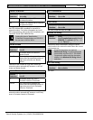
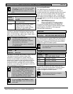
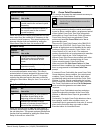
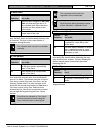
CrystalTime Adj
6.9 Cross Point Parameters
This section discusses the requirements necessary to
program Cross Point functions.
Default: No
Selection:
Yes or No
Yes Set the clock time control on the
control panel to the on-board crystal
frequency.
No Do not set the clock time control on
the control panel to the on-board
crystal frequency.
When set to Yes, the control panel switches its clock
time control from the traditional AC frequency to the
on-board crystal frequency. This prompt replaces the
alternate function that was enabled by setting the
Silent Alarm Relay for Area 4 to a value of 60.
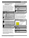
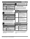
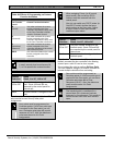
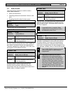
Perimeter Relay
Default: No
Selection:
Yes or No
Yes Change the function of the area-wide
fail-to-close relays to follow the
perimeter armed states of their
areas.
No The area-wide fail-to-close relay
operates normally.
When set to Yes, the A# Fail to Close relay becomes
an area-wide perimeter armed relay. This relay is
activated when all areas assigned to the same relay
have perimeter points that are armed. This prompt
replaces the alternate function that was enabled by
setting the Silent Alarm Relay for Area 7 to a value of
63.
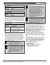
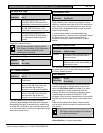
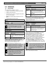
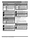
Early Armed Relay
Default: No
Selection:
Yes or No
Yes Change activation of Area Armed or
Perimeter Armed Relay to the
beginning of the exit delay time.
No Maintain the activation of Area
Armed or Perimeter Armed Relay at
the end of the exit delay time.
When this prompt is set to Yes, the Area Armed or
Perimeter Armed Relay activates at the beginning of
the exit delay time. This prompt replaces the alternate
function that was enabled by setting the Silent Alarm
Relay for Area 8 to a value of 64.
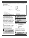
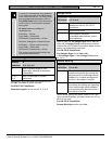
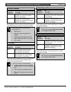
Use the Cross Point function on non-fire
points only.
The Cross Point option reduces false alarms. Points
can be programmed so that the control panel needs
to see an Alarm condition within a programmed period
of time (called Cross Point Time) from at least two
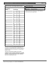
points within a Cross Point Group (
Table 43) before
Cross Point Alarm Events are generated. These
points must have P## Cross Point set to Yes to
generate this event.
There are 31 Cross Point Groups in the D9412GV2
and ten in the D7412GV2. Each Cross Point Group
consists of eight points and is identified by the point
numbers in them (for example, Cross Points 1 to 8,
Cross Points 9 to 16, and so on). The maximum
number of points that can be programmed to meet the
Cross Point criteria is two. Point numbers from
different Cross Point Groups do not affect each other.
Refer to
Table 43 for a complete listing of Cross
Points comprising each Cross Point Group.
When any point with P## Cross Point set to Yes
detects an alarm condition, the control panel starts a
timer as programmed in the Cross Point Time
prompt.
If a second Cross Point within the same Cross Point
Group detects an alarm condition, the control panel
creates a Cross Point Alarm Event for both points,
provided both points activate inside the Cross Point
Window. A Cross Point is considered to be in alarm
when it meets the criteria for Instant Alarm response.
The Cross Point index must have P## Pt Response
set to a value that generates an instant alarm
response.
If a single Cross Point detects an alarm and stays
faulted throughout the duration of the Cross Point
Window, a standard Alarm Report is generated for
that point.
Conversely, if a single Cross Point detects an alarm,
then restores, and no other conditions occur, an
Unverified Event is generated for that point. A second
alarm on the first point does not create an Alarm
Event but rather an Unverified Event.


