


D9412GV2/D7412GV2 | Program Entry Guide | 6.0 GV2AUX EN | 127
Bosch Security Systems, Inc. | 10/08 | F01U003636-04
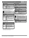
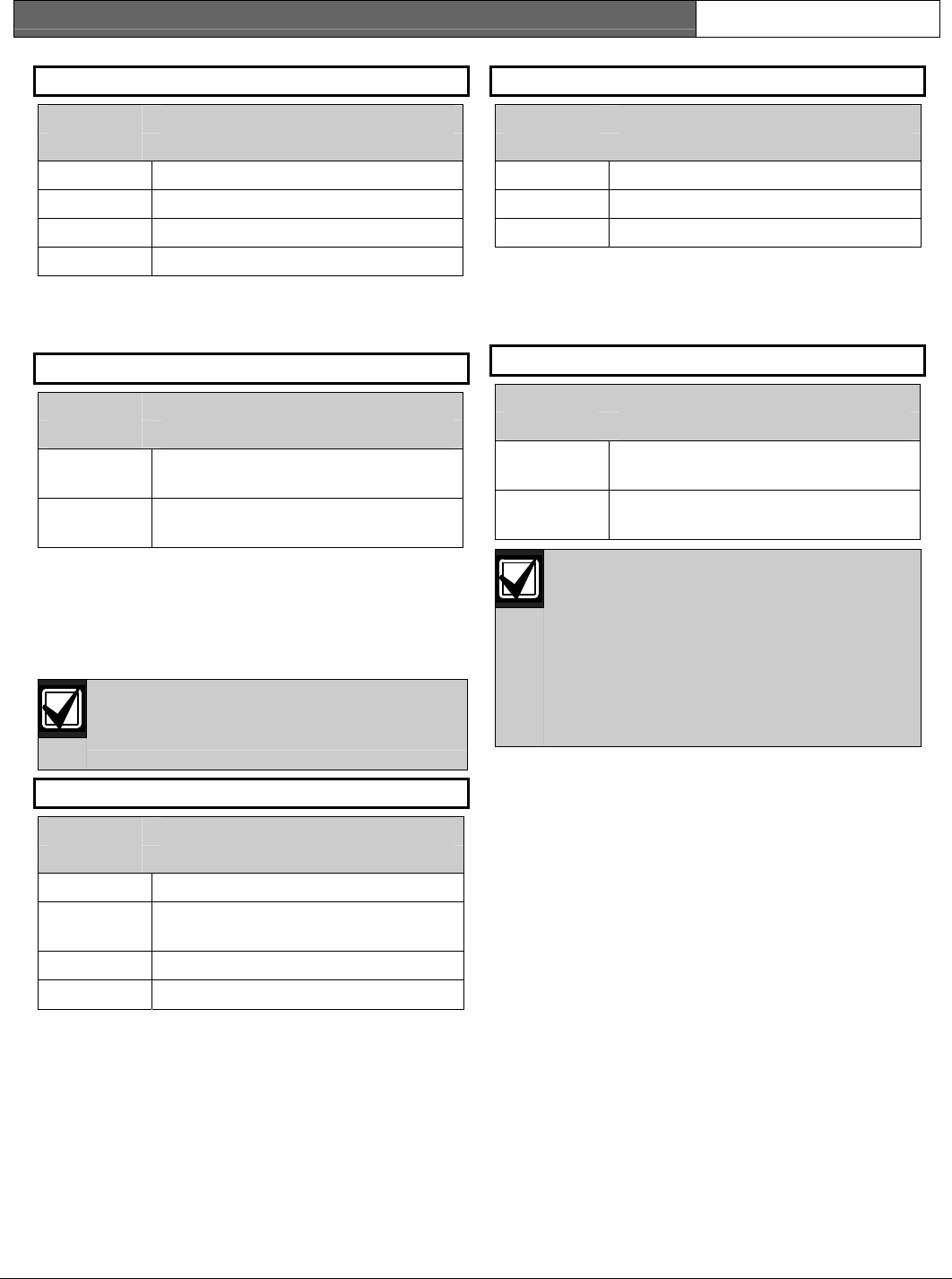
Parity/Stop DTR Control
Default: No/1 Default: On
Selection: No/1, No/2, Odd/1, Even/1 Selection: On, AutoD, Off
No/1 No parity, 1 stop bit On Sets DTR to on (hardware control).
No/2 No parity, 2 stop bits AutoD Sets this to Auto DTR.
Odd/1 Odd parity, 1 stop bit Off Sets DTR off (hardware control).
Even/1 Even parity, 1 stop bit
This item determines how the Data Terminal Ready
(DTR) Control parameters are defined for the D9133.
Pressing the [SPACE] bar on the D5200 toggles
through the available options.
This prompt addresses two items: parity and the
number of stop bits. Pressing the [SPACE] bar on the
D5200 toggles through the available options.
Status Rate
9133 Supervision
Default: 0
Default: No
Selection: 0 to 255
Selection: Yes or No
Status information is sent only when
requested.
0
Supervise the serial interface
module (SIM).
Yes
Status information is sent at the
interval programmed.
1 to 255
Do not supervise the serial interface
module (SIM).
No
This item determines whether the serial interface
module (SIM) is supervised or not. If the SIM is
supervised, disconnecting the SIM from the control
panel creates a Trouble SDI 80 Event and the
keypad annunciates a trouble tone (if programmed)
and displays SERVC SDI 80.
If the Status Rate is set to a value less
than 10, and 1 to 6 SDI devices are
Trouble SDI 80 Reports are always sent
using the account number for Area 1.
RTS Control
Default: On
Selection: On, AutoX, Off, AutoR
On Sets RTS to on (hardware control).
AutoX
Automatically enables Xon/Xoff
(software control).
Off Sets RTS off (hardware control).
AutoR Sets this to Auto RTS.
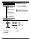
This item determines how the Request To Send
(RTS) Control parameters are defined for the serial
interface module (SIM). Pressing the [SPACE] bar on
the D5200 toggles through the available options.
connected to the system, the fastest the
control panel can send the status
information is in approximately 1 sec. If
more than six SDI devices are connected
to the control panel, the fastest the
control panel can send the information is
in approximately 1.5 sec to 2 sec.
This item determines how often the default status
information is sent to the serial interface module
(SIM). The status information includes:
•
•
•
•
The current point status (normal or off-normal),
The control panel’s area status (Master Armed,
Master Instant Armed, Perimeter Delay Armed,
Perimeter Instant Armed, Disarmed, Area Entry
Delay, Perimeter Entry Delay, Area Exit Delay,
and Perimeter Exit Delay)
The control panel status (AC Fail, Battery
Missing, AC Restore, Battery Low, and so on)
Relay status (relay on or relay off)
Entries are in 100 millisecond increments. If a 5 is
entered, the status information is sent every 500
milliseconds (or 0.5 sec). An entry of 10 equals 1 sec.