


D9412GV2/D7412GV2 | Program Entry Guide | 6.0 GV2AUX EN | 132
Bosch Security Systems, Inc. | 10/08 | F01U003636-04
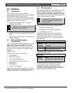
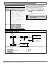
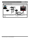
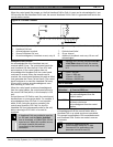
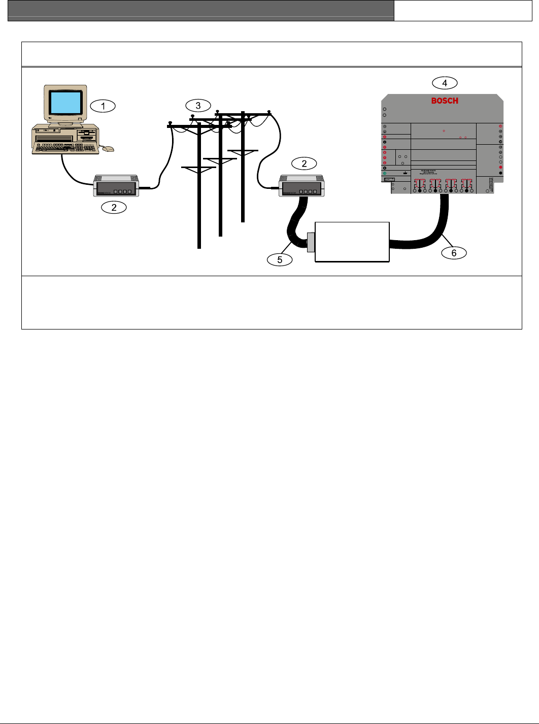
Figure 9: External Modem Connection
P3
P2
1 2 4 8
SER RX TX RX TX BUS
SDI
PWR
SDI
A
SDI
B
SDI
COM
DX4010i
or
D9133DC
EART H G ROUN D
COMMON
BATTERY NEGATIVE ONLY
BATT ERY POSI TIVE ONLY
RELAY A
RELAY B
RELAY C
+ AUX POW ER
CLASS 2 TRANSFORMER
16.5 VAC 40 VA 60 Hz
Model D1640
Internally Fus ed - Do not short
Requires U nswitched Outlet
Do not share with other equipment
GROUND FAULT DETECT
Enabled
Disa bled
PHONE
LED
RED
ON when
comm u ni ca ti ng
OFF when idle
Digital Alarm Communicato r Transmitter
WARNING!
Multi-B attery ins tallatio n requires
Model D122 Dual Battery Harness.
Improper installation can be a fire
hazard.
Battery: Replace every 3 to
5 years with Model D126, 12 V
7 Amp Hr Lead Acid Battery
D9412GV2 Control/Communicator is UL Listed For Central Station, Local, Remote Station and
Household Fire Alarm, and Central Station, Local, Police Station Connect, Household Burglar Alarm
and En crypted Line Se curit y when comm unica ting vi a a net work.
System is intended to be chec ked by a Qualified Technicia n at least every 3 yea rs.
The type s of initiating circuits the pane l has been appro ved for are A, M, W, SS.
VOLTAGE RANGES
Open 3.7 - 5.0 VDC
Normal 2.0 - 3.0 VD C
Short 0.0 - 1.3 VDC
GRN
Reset Pin
Disable a ll except Battery
Charging and Programmin g
PERI PHERA L DEVIC E CONNE CTION S
RED POWER +
YELLOW DATA BUS A
GR EEN DATA B US B
BLACK COMMON
ZONEX OUT 1
ZONEX IN 1
N.F.P.A.
Style 3.5
Signaling
Line
Circuits
D5200
PROG CONN
F01U003643B
Point 8
S3 Option
1211 13
Point 1Point 2
1514 16
Point 3Point 4
1817 19
Point 5Point 6
2120 22
Point 7Point 8
LEDs Off When Normal
Charging Stat us
Low Battery - 12.1 VDC
YEL
RED
10.2 VDC - Ba ttery Load Shed
This equipment should be installed in accordanc e with the NFPA 70 (Nationa l Electrical Code)
and NFPA 72 (National Fir e Alarm Code) for Local, Centr al Station, Remote Station, Proprietary and
Household Fire Warning Systems and under the limits of the Local Authority Having Jurisdiction
(National Fire Pro tection Association, Batterm arch Park, Quincy, MA 02269). Pr inted information
describing proper installation, operation, testing, maintenance, evacuation planning and repair
service is to be pr ovided with this equipmen t.
D9412GV2
26
25
ZONEX POW ER +
24
ZONEX COMMON
23
PHON E L IN E SEI ZE D
Closed = 1KW EOL
Normal Operation
Open =AB-12 UL
Bell Box 220 KW
TIP
RING
TELCO CORD
MODEL D161
SDI C onnector
ZONEX OUT 2
ZONEX IN 2
Refer to D9412GV2/D7412GV2 Approved Applications Compliance Guide (P/N: F01U003639___)
For System Wiring Diagram , Issue A
Refer to D9412GV2/D7412GV2 Approved Applications Compliance Guide (P/N: F01U003639___)
For Compatible Smoke Detectors
POWER SUPPLY REQUIREMENTS
The Power Supply provides a maximum of 1.4 Amps for the Control Panel and all
Acces sory De vices. Fo r System Loading , refer to D9412GV2/ D7412 GV2
Oper ation and Installat ion Gui de (P/N: F01U003 641___) .
(P/N: F0 1U003641 ) for Power Requir ements relatin g to Terminal s 6 and 7 .
CAUTI ON:
See D9412GV2/D7412GV2 Operation and Installation Guide
All ext ernal connec tions exc ept Terminal 5 (batter y positive ) are inheren tly power
limit ed. Require ments for bat tery standb y time might reduc e allowabl e output.
CAUTION:
Avoid damage to Panel.
Do not con nect 24 V to termi nals.
Maximu m charging curren t 1.4 A
PRO GRAMM ABLE
ALARM OUTPUTS
Term in a ls
SWITCHED AUX
and67
Termi nal
8
4 - D9412GV2/D7412GV2 Control Panel
1 - PC running Remote Programming Software
(RPS)
5 - Standard null modem cable
2 - Modem
6 - SDI bus
3 - PSTN