


Page 858 of 894 QPC841 Quad Serial Data Interface card
553-3001-211 Standard 2.00 September 2004
QSDI cards are housed in the following modules:
• NT5D21 Core/Network module (slots 0 through 7)
• NT6D39 CPU/Network module (slots 1 through 9, and 13)
• NT6D60 Core module (slots 0 through 5)
• NT8D35 Network module (slots 5 through 13)
• NT9D11 Core/Network module (slots 0 through 8)
Note: When a QSDI card is installed in an NT6D60 Core module, an
NT8D34 CPU module, or slot 13 of an NT6D39 CPU/Network module
in a dual-CPU system, any input/output I/O device connected to the card
does not function when the CPU in that module is inactive.
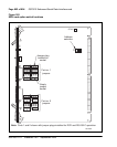
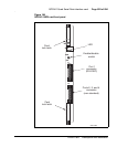
Physical description
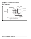
The QPC841 QSDI card is a printed circuit board measuring 31.75 cm by
25.4 cm (12.5 in. by 10 in.). The front panel is 2.54 cm (1 in.) thick. See
Figure 184 on page 859.
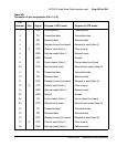
Up to four QSDI boards can be used in a system, allowing a total of sixteen
asynchronous serial ports. The four serial ports on each card are addressed as
two pairs of consecutive addresses (0 and 1, 2 and 3, and so on up to 14 and
15). The pairs need not be consecutive. For example: pairs 0 and 1, and 4 and
5 could be used.
The card front panel has two connectors, J1 and J2. Connector J1 is used for
port 1 while connector J2 is used for ports 2, 3, and 4. It also has an Enable/
Disable (ENB/DIS) switch and a red LED. The LED indicates that the card
has been disabled. It is lit when the following occurs:
• the ENB/DIS switch is set to DIS
• all of the ports on the card are disabled in software
• none of the card ports are configured in software