


NT5D97 Dual-port DTI2/PRI2 card Page 351 of 894
Circuit Card Description and Installation
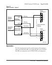
Case 3 - The network shelf is full, one port of a QPC414 network card is
connected to a digital trunk, and the second is connected to a peripheral
buffer. This arrangement is repeated for another QPC414. The digital trunks
are located in a shelf that provides only power.
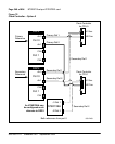
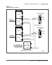
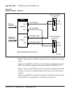
In this case, the peripheral buffers will have to be re-assigned, so that each
pair of buffers will use both ports of the same QPC414 card. The other
QPC414 card can then be replaced by the NT5D97 DDP2.
Procedure 14
Installing the NT5D97
1 Determine the cabinet and shelf location where the NT5D97 is to be
installed. The NT5D97 can be installed in any card slot in the Network
bus.
2 Unpack and inspect the NT5D97and cables.
3 If a DDCH is installed, refer to the section “Removing the NT5D97” on
page 352.
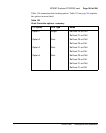
4 Set the option switches on the NT5D97 card before installation. Refer to
“NT5D97AA/AB DIP switch settings” on page 328.
The ENB/DIS (enable/disable faceplate switch) must be OFF (DIS) when
installing the NT5D97, otherwise a system initialize can occur. The ENB/
DIS on the NT5D97 corresponds to the faceplate switch on the QPC414
Network card.
5 Install NT5D97 card in the assigned shelf and slot.
6 Set the ENB/DIS faceplate switch to ON.
If the DDCH is installed, the DDCH LED should flash three times.
7 If required, install the I/O adapters in the I/O panel.
CAUTION
The static discharge bracelet located inside the
cabinet must be worn before handling circuit cards.
Failure to wear the bracelet can result in damage to
the circuit cards.