


NTAK10 2.0 Mb DTI card Page 711 of 894
Circuit Card Description and Installation
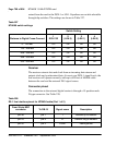
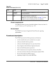
Power requirements
The 2MB DTI obtains its power from the backplane. It draws less than 2 A
on +5 V, 50 mA on +15 V and 50 mA on –15 V.
Environment
The NTAK10 card meets all applicable Nortel Networks operating
specifications.
Functional description
The NTAK10 provides the following features and functions:
• a clock controller that can be switched in as an option
• software-selectable A/µlaw operation
• software-selectable digital pads on a per channel basis
• frame alignment and multiframe alignment detection
• frame and multiframe pattern generation
• CRC-4 transmission and reception (software selectable)
• card status and alarm indication with faceplate-mounted LEDs
• Periodic Pulse Metering (PPM) counting
• outpulsing of digits on any of the ABCD bits
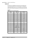
Flashing
(Green)
The clock controller is switched on and locking onto the
primary reference.
Off The clock controller is switched off.
Note: See “Clock controller interface” on page 717 in this
chapter for more on tracking and free-run operation.
Table 229
NTAK10 LED states (Part 2 of 2)
LED State Definition