


Page 620 of 894 NT8D15 E&M Trunk card
553-3001-211 Standard 2.00 September 2004
• Software control of A/µ-Law mode.
• Software control of digit collection.
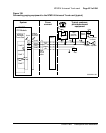
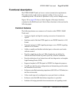
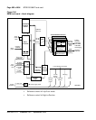
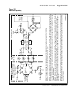
Figure 140
E&M trunk card – block diagram
Input/output
interface
control
Micro-
controller
DS-30X
interface
5.12 MHz
clock
Tx PCM
Async card
LAN link
Front
panel
LED
Card LAN
interface
Codec
PCM
Analog
hybrid
XFMR
Signaling relays
(ringing, battery
reversal)
Trunk interface units 0–3
Line interface unit power
Rx PCM
1 kHz
frame sync
Con-
troller
card
Trunk
signaling
interface
Control
logic
Reg
Signaling
and status
Address/
data bus
553-6201
Power
supplies
+5 V dc
analog
hybrid
±15 V dc
analog
power
+8.5 V dc
+5 V dc logic power
Ringing
Ð 48 V dc
battery
Rsync
Tip/ring
(2/4 wire)
Voice
band
E&M
Sup.
signaling
Facility
services
interfaces
(2-W E&M,
4-W E&M,
and Paging)
Signaling
interface
Loop current/
dialpulse detect
Card slot
address
Back-
plane