


NTBK50 2.0 Mb PRI card Page 769 of 894
Circuit Card Description and Installation
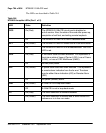
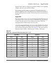
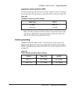
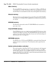
Impedance matching (Switch SW2)
The line interface provides for the use of either 75 ohms coaxial or 120 ohms
twisted pair cable. The impedance is selected by SW2, as shown in Table 246.
Note: The ON position for all the switches is toward the bottom of the
card. This is indicated by a white dot printed on the board next to the
bottom left corner of each individual switch.
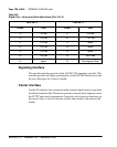
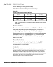
Carrier grounding
NTBK50 enables the shield of the Tx and/or Rx pairs of the carrier to be
selectively grounded. Closing (down position) the on-board switch applies
FGND to the appropriate carrier cable shield. The switch settings are shown
in Table 247.
Table 246
Impedance matching switch settings
Cable Type SW 2-1
75 ohms Down (On)
120 ohms Up (Off)
Table 247
Carrier Shield grounding switch settings
Switch Down (On) Up (Off)
SW 4 – 1 Rx – FGND Rx – OPEN
SW 4 – 2 Tx – FGND Tx – OPEN