


NT5D33 and NT5D34 Lineside E1 Interface cards Page 273 of 894
Circuit Card Description and Installation
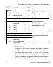
Two levels of alarm severity exist for bit errors. Different threshold and
duration settings must be established for each level.
When the first level of severity is reached (alarm level 1), the MMI causes the
following:
• the external alarm hardware activates
• he RED ALARM LED on the faceplate will be lit
• an alarm message will be displayed on the MMI terminal
• an entry will be created in the alarm log and printed to the MMI port
When the second level of severity is reached (alarm level 2), the MMI will
perform all functions at alarm level 1. In addition, the LEI enters
line-conditioning mode. In this mode, the LEI sends either “on-hook” or
“off-hook” signals for all 30 ports to the CS 1000S, CS 1000M, and
Meridian 1, depending on how the dip switch for line processing is set (dip
switch 2, position 6). See Table 94 on page 258.
If the MMI detects E1-link failures for any of the other conditions monitored
(out-of-frame, excess frame slips, loss-of-signal, and blue alarm condition),
the LEI automatically performs all alarm level 2 functions. The MMI also
sends a yellow alarm to the far-end LTU. Alarms may be set to self-clear
when the alarm condition is no longer detected. See “Set Clearing” on
page 282.
All alarms activated produce a record in the alarm log. The alarm log
maintains records for the most recent 100 alarms, and can be displayed,
printed, and cleared. The alarm log displays or prints the alarms in descending
chronological order, beginning with the most recent alarm. Notifications in
the alarm log include the date and time of the alarm’s occurrence.
E1 Performance Counters and Reports
The MMI maintains performance error counters for the following E1
conditions:
• errored seconds
• bursty seconds
• unavailable seconds