


Option settings Page 131 of 894
Circuit Card Description and Installation
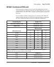
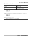
both switches are shown in Table 42. To avoid system problems, switches
SW15 and SW16 must not be configured identically.
* To enable ports 1 and 2, set SW15 position 1 to ON. To enable ports 3 and 4, set SW16 position 1 to ON.
+
For each X, the setting for this switch makes no difference, because it is not used.
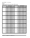
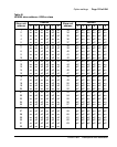
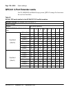
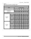
DTE/DCE mode
Each serial port can be configured to connect to a terminal (DTE equipment)
or a modem (DCE equipment). Instructions for setting the DTE/DCE
switches SW2, SW3, SW4, SW5, SW6, SW7, SW8, and SW9 are shown in
Table 43.
Example: Port 1 is changed from DTE to DCE by reversing every switch
position on SW3 and SW2; i.e., switches that were off for DTE are turned on
for DCE, and switches that were on for DTE are turned off for DCE.
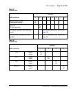
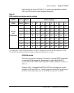
Table 42
QSDI paddle board address switch settings
SW15 Port 1 Port 2 Switch settings
SW16 Port 3 Port 4 1* 2
+
3 4 5 6 7 8
Device
pair
addresses
0 1 E X off off off off off off
2 3 E X off off off off off on
4 5 E X off off off off on off
6 7 E X off off off off on on
8 9 E X off off off on off off
10 11 E X off off off on off on
12 13 E X off off off on on off
14 15 E X off off off on on on