


Page 262 of 894 NT5D33 and NT5D34 Lineside E1 Interface cards
553-3001-211 Standard 2.00 September 2004
Alternatively, all LEI connections can be made at the main distribution frame
instead of connecting the NT5D35AA or NT5D36AA LEI card external I/O
cable at the I/O panel. This eliminates these card slot restrictions.
Cabling the LEI card
After the dip switches are set and the LEI installed into the selected card slots,
the LEI can be cabled to the LTU equipment, the MMI terminal or modem
(optional), an external alarm (optional), and other LEIs for daisy chaining use
of the MMI terminal (optional).
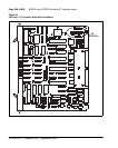
The LEI is cabled from its backplane connector through connections from the
motherboard circuit card only to the I/O panel on the rear of the IPE module.
No cable connections are made from the daughterboard circuit card. The
connections from the LEI to the I/O panel are made with the NT8D81AA Tip
and Ring cables provided with the IPE module.
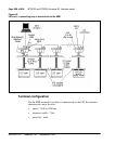
Cabling from the I/O panel with the NT5D35AA or NT5D36AA
lineside E1 I/O cable
In a twisted-pair E1 installation, make the connection from the I/O panel to
the E1 link and other external devices with the NT5D35AA lineside E1 I/O
cable.
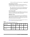
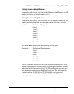
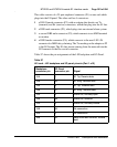
This cable consists of a 25-pair amphenol connector (P1) on one end which
plugs into the I/O panel. The other end has four connectors:
1 a DB15 male connector (P2), which plugs into the E1 line
2 a DB9 male connector (P3), which plugs into an external alarm system
3 a second DB9 male connector (P5), which connects to an MMI terminal
or modem
4 a DB9 female connector (P4), which connects to the next LEI’s P4
connector for MMI daisy chaining
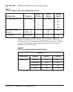
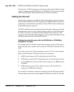
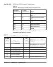
In a coaxial E1 installation, make the connection from the I/O panel to the E1
link and other external devices through the NT5D36AA lineside E1 I/O cable.