


NT8D09 Analog Message Waiting Line card Page 549 of 894
Circuit Card Description and Installation
Configuration
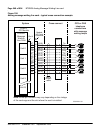
This section outlines the procedures for configuring the switches and jumpers
on the NT8D09 Analog Message Waiting Line card and configuring the
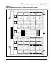
system software to properly recognize the card. Figure 109 on page 551
shows where the switches and jumper blocks are located on this board.
Jumper and switch settings
The NT8D09 Analog Message Waiting Line card has no user-configurable
jumpers or switches. The card derives its address from its position in the
backplane and reports that information back to the CPU through the LAN
Link interface.
Software service changes
Individual line interface units on the NT8D09 Analog Message Waiting Line
card are configured using the Analog (500/2500-type) Telephone
Administration program LD 10.
The message waiting feature is enabled by entering data into the customer
data block using LD 15. See Software Input/Output: Administration
(553-3001-311) for LD 10 and LD 15 service change instructions.
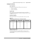
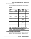
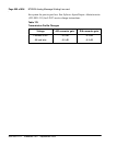
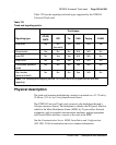
Analog message waiting line cards with a vintage later than NT8D09AK
provide a fixed +2 dB transmission profile change in the gain of the D/A
convertor. See Table 178 on page 550.
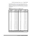
This transmission profile change is used for control of end-to-end connection
loss. Control of such loss is a major element in controlling transmission
parameters such as received volume, echo, noise, and crosstalk. The loss plan
for the analog message waiting line card determines port-to-port loss between
an analog line card unit (port) and other IPE ports. LD 97 is used to configure